ISP1583 Ver la hoja de datos (PDF) - NXP Semiconductors.
Número de pieza
componentes Descripción
Fabricante
ISP1583 Datasheet PDF : 100 Pages
| |||
NXP Semiconductors
ISP1583
Hi-Speed USB peripheral controller
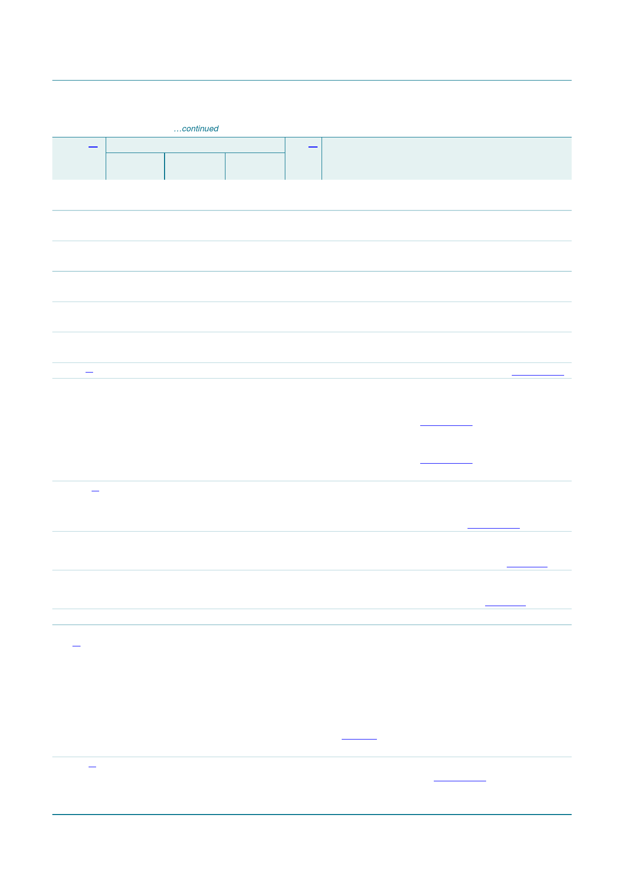
Table 3. Pin description …continued
Symbol[1] Pin
Type[2] Description
ISP1583BS ISP1583ET; ISP1583ET1
ISP1583ET2
DATA10 48
A10
A8
I/O bit 10 of the bidirectional data bus
bidirectional pad; 4 ns slew-rate control; TTL; 5 V tolerant
DATA11 49
A9
C4
I/O bit 11 of the bidirectional data bus
bidirectional pad; 4 ns slew-rate control; TTL; 5 V tolerant
DATA12 50
B8
B7
I/O bit 12 of the bidirectional data bus
bidirectional pad; 4 ns slew-rate control; TTL; 5 V tolerant
DATA13 51
A8
A7
I/O bit 13 of the bidirectional data bus
bidirectional pad; 4 ns slew-rate control; TTL; 5 V tolerant
DATA14 52
B7
C6
I/O bit 14 of the bidirectional data bus
bidirectional pad; 4 ns slew-rate control; TTL; 5 V tolerant
DATA15 53
A7
C5
I/O bit 15 of the bidirectional data bus
bidirectional pad; 4 ns slew-rate control; TTL; 5 V tolerant
VCC(I/O)[4] 54
B6
B6
-
I/O pad supply voltage (1.65 V to 3.6 V); see Section 8.16
VBUS
55
B5
A6
A
USB bus power sensing input — Used to detect
whether the host is connected or not; connect a 1 µF
electrolytic or tantalum capacitor and a 1 MΩ pull-down
resistor to ground; see Section 8.14
VBUS pulsing output — In OTG mode; connect a 1 µF
electrolytic or tantalum capacitor and a 1 MΩ pull-down
resistor to ground; see Section 8.14
5 V tolerant
VCC1V8[4] 56
A6
B5
-
voltage regulator output (1.8 V ± 0.15 V); tapped out
voltage from the internal regulator; this regulated voltage
cannot drive external devices; decouple this pin using
4.7 µF and 0.1 µF capacitors; see Section 8.16
XTAL2
57
A5
A5
O
crystal oscillator output (12 MHz); connect a fundamental
parallel-resonant crystal; leave this pin open when using
an external clock source on pin XTAL1; see Table 100
XTAL1
58
A4
A4
I
crystal oscillator input (12 MHz); connect a fundamental
parallel-resonant crystal or an external clock source
(leaving pin XTAL2 unconnected); see Table 100
DGND
59
B4
B4
-
digital ground
MODE0/ 60
A3
C2
I/O Mode selection input 0 — Selects the read/write strobe
DA1[3]
functionality in generic processor mode during power-up:
• LOW: for the Freescale mode; the function of pin 19 is
RW_N and pin 20 is DS_N
• HIGH (connect to VCC(I/O)): for the 8051 mode; the
function of pin 19 is RD_N and pin 20 is WR_N
Address selection output — Selects the Task File
register of an ATA/ATAPI device during normal operation;
see Table 61
bidirectional pad; 10 ns slew-rate control; TTL; 5 V tolerant
VCC(3V3)[4] 61
B3
B3
-
regulator supply voltage (3.3 V ± 0.3 V); this pin supplies
the internal regulator; see Section 8.16
ISP1583_7
Product data sheet
Rev. 07 — 22 September 2008
© NXP B.V. 2008. All rights reserved.
10 of 99
Share Link: 