M80C186 Ver la hoja de datos (PDF) - Intel
Número de pieza
componentes Descripción
Fabricante
M80C186 Datasheet PDF : 59 Pages
| |||
M80C186
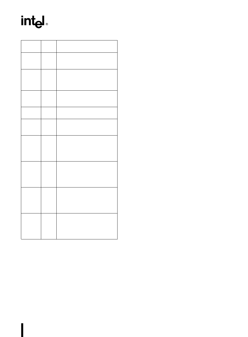
Table 2 Status Word Bit Functions
Bit
Position
Name
Function
0
CF Carry Flag Set on high-order
bit carry or borrow cleared
otherwise
2
PF Parity Flag Set if low-order 8
bits of result contain an even
number of 1-bits cleared
otherwise
4
AF Set on carry from or borrow to
the low order four bits of AL
cleared otherwise
6
ZF Zero Flag Set if result is zero
cleared otherwise
7
SF Sign Flag Set equal to high-
order bit of result (0 if positive
1 if negative)
8
TF Single Step Flag Once set a
single step interrupt occurs
after the next instruction
executes TF is cleared by the
single step interrupt
9
IF Interrupt-enable Flag When
set maskable interrupts will
cause the CPU to transfer
control to an interrupt vector
specified location
10
DF Direction Flag Causes string
instructions to auto decrement
the appropriate index register
when set Clearing DF causes
auto increment
11
OF Overflow Flag Set if the
signed result cannot be
expressed within the number
of bits in the destination
operand cleared otherwise
Instruction Set
The instruction set is divided into seven categories
data transfer arithmetic shift rotate logical string
manipulation control transfer high-level instruc-
tions and processor control These categories are
summarized in Figure 4
An M80C186 instruction can reference anywhere
from zero to several operands An operand can re-
side in a register in the instruction itself or in memo-
ry Specific operand addressing modes are dis-
cussed later in this data sheet
Memory Organization
Memory is organized in sets of segments Each seg-
ment is a linear contiguous sequence of up to 64K
(216) 8-bit bytes Memory is addressed using a two-
component address (a pointer) that consists of a 16-
bit base segment and a 16-bit offset The 16-bit
base values are contained in one of four internal
segment register (code data stack extra) The
physical address is calculated by shifting the base
value LEFT by four bits and adding the 16-bit offset
value to yield a 20-bit physical address (see Figure
5) This allows for a 1 MByte physical address size
All instructions that address operands in memory
must specify the base segment and the 16-bit offset
value For speed and compact instruction encoding
the segment register used for physical address gen-
eration is implied by the addressing mode used (see
Table 3) These rules follow the way programs are
written (see Figure 6) as independent modules that
require areas for code and data a stack and access
to external data areas
Special segment override instruction prefixes allow
the implicit segment register selection rules to be
overridden for special cases The stack data and
extra segments may coincide for simple programs
11
Share Link: 