M28W320CT09GB1T Ver la hoja de datos (PDF) - STMicroelectronics
Número de pieza
componentes Descripción
Fabricante
M28W320CT09GB1T Datasheet PDF : 42 Pages
| |||
M28W320CT, M28W320CB
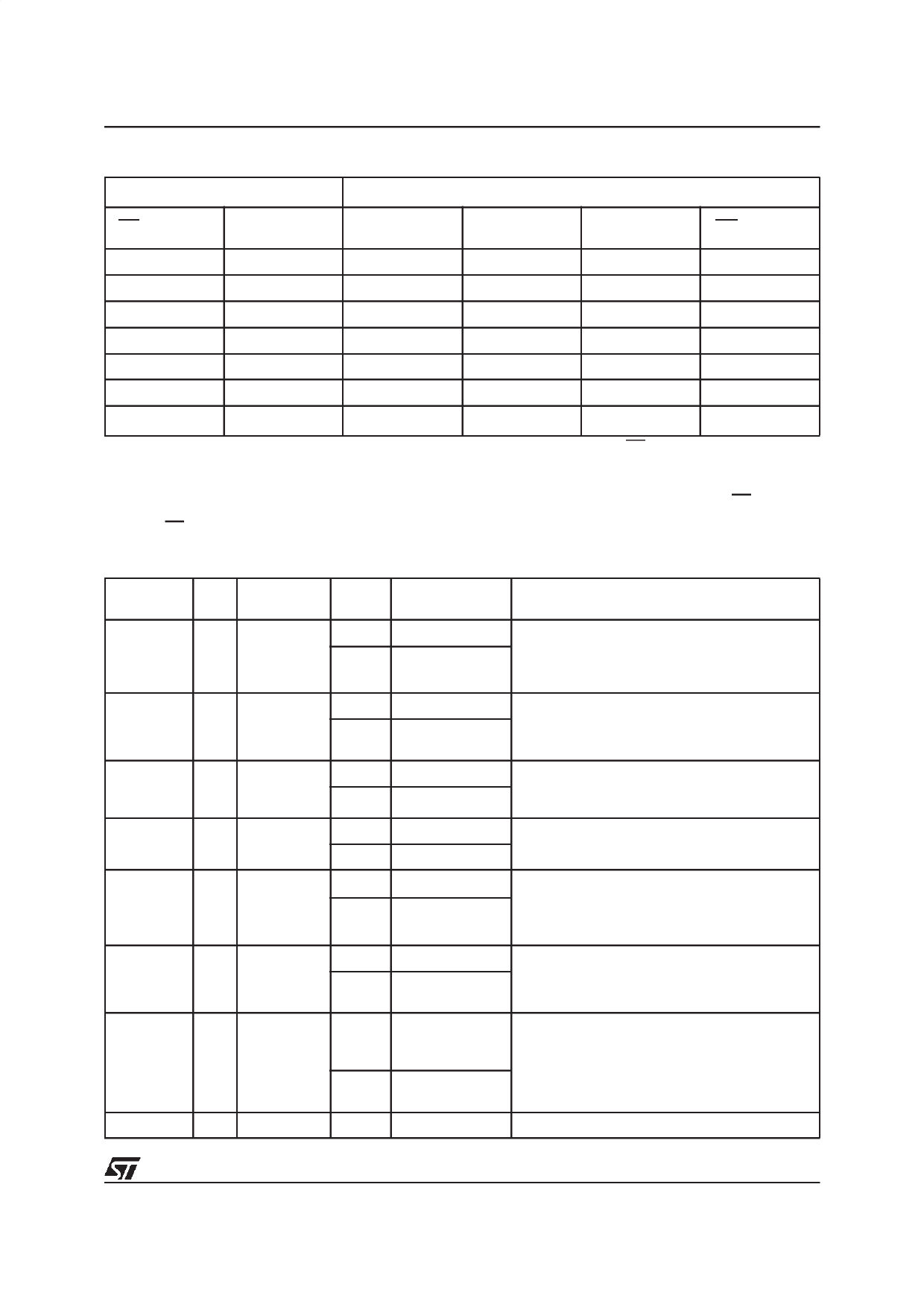
Table 11. Protection States (1)
Current State (2)
Next State After Event (3)
(WP, DQ1, DQ0)
Program/Erase
Allowed
Protect
Unprotect
Lo ck
WP transition
100
yes
101
100
111
000
101
no
101
100
111
001
110
yes
111
110
111
011
111
no
111
110
111
011
000
yes
001
000
011
100
001
no
001
000
011
101
011
no
011
011
011
111 or 110 (4)
Note: 1. All blocks are protected at power-up, so the default configuration is 001 or 101 according to WP status.
2. Current state and Next state gives the protection status of a block. The protection status is defined by the write protect pin and by
DQ1 (= 1 for a locked block) and DQ0 (= 1 for a protected block) as read in the Read Electronic Signature instruction with A1 = VIH
and A0 = VIL.
3. Next state is the protection status of a block after a Protect or Unprotect or Lock command has been issued or after WP has changed
its logic value.
4. A WP transition to VIH on a locked block will restore the previous DQ0 value, giving a 111 or 110.
Table 12. Status Register Bits
Mnemonic Bit
Name
Logic
Level
Definition
Note
P/ECS
’1’ Ready
7 P/E.C. Status
’0’ Busy
Indicates the P/E.C. status, check during
Program or Erase, and on completion before
checking bits b4 or b5 for Program or Erase
Success.
ESS
Erase
6 Suspend
Status
’1’ Suspended
’0’
In progress or
Completed
On an Erase Suspend instruction P/ECS and
ESS bits are set to ’1’. ESS bit remains ’1’ until an
Erase Resume instruction is given.
’1’ Erase Error
ES bit is set to ’1’ if P/E.C. has applied the
ES
5 Erase Status
maximum number of erase pulses to the block
’0’ Erase Success without achieving an erase verify.
PS
4
Program
Status
’1’ Program Error
PS bit set to ’1’ if the P/E.C. has failed to program
’0’ Program Success a word.
VPPS
3 VPP Status
’1’ VPP Invalid, Abort VPPS bit is set if the VPP voltage is below VPPLK
when a Program or Erase instruction is executed.
’0’ VPP OK
VPP is sampled only at the beginning of the
erase/program operation.
PSS
Program
2 Suspend
Status
’1’ Suspended
’0’
In Progress or
Completed
On a Program Suspend instruction P/ECS and
PSS bits are set to ’1’. PSS remains ’1’ until a
Program Resume Instruction is given.
BPS
Block
1 Protection
Status
Program/Erase on
’1’ protected Block, BPS bit is set to ’1’ if a Program or Erase
Abort
operation has been attempted on a protected
’0’
No operation to block.
protected blocks
0 Reserved
Note: Logic level ’1’ is High, ’0’ is Low.
11/42
Share Link: 