M28W320CT09GB1T Ver la hoja de datos (PDF) - STMicroelectronics
Número de pieza
componentes Descripción
Fabricante
M28W320CT09GB1T Datasheet PDF : 42 Pages
| |||
M28W320CT, M28W320CB
The suggested flow charts for programs that use
the programming, erasure and program/erase
suspend/resume features of the memories are
shown from Figures 11, 12, 13, 14 and 15.
Protection Register Program (PRP)
The Protection Register Program uses two write
cycles. The first command written is the protection
program command C0h. The second write opera-
tion latches the Address and the Data to be written
to the Protection Register (see Protection Register
and Security Block) and start the PE/C. Read op-
erations output the Status Register content after
the programming has started. The 64 bits user
programmable Segment (85h to 88h) are pro-
grammed 16 bits at a time, it can be protected by
the user programming bit 1 of the Protection Lock
register. The bit 1 of the Protection Lock register
protect the bit 2 of the Protection Lock Register.
Writing the bit 2 of the Protection Lock Register will
result in a permanent protection of the Security
Block. Attempting to program a previously protect-
ed protection Register will result in a status regis-
ter error (bit 1 and bit 4 of the status register will be
set to ’1’). The protection of the Protection Register
and/or the Security Block is not reversible.
The Protection Register Program cannot be sus-
pended.
Block Protect (BP)
The BP instruction use two write cycles. The first
command written is the protection setup 60h. The
second command is block Protect command 01h.
The address within the block being protected must
be given in order to write the protection state. If the
second command is not recognized by the C.I the
bit 4 and bit 5 of the status register will be set to in-
dicate a wrong sequence of commands. To read
the status register write the RSR command.
Block Unprotect (BU)
The instruction use two write cycles. The first com-
mand written is the protection setup 60h. The sec-
ond command is block Unprotect command d0h.
The address within the block being unprotected
must be given in order to write the unprotection
state. If the second command is not recognized by
the C.I the bit 4 and bit 5 of the status register will
be set to indicate a wrong sequence of com-
mands. To read the status register write the RSR
command.
Block Lock (BL)
The instruction use two write cycles. The first com-
mand written is the protection setup 60h. The sec-
ond command is block Lock command 2Fh. The
address within the block being Locked must be
given in order to write the Locking state. If the sec-
ond command is not recognized by the C.I the bit 4
and bit 5 of the status register will be set to indicate
a wrong sequence of commands. To read the sta-
tus register write the RSR command.
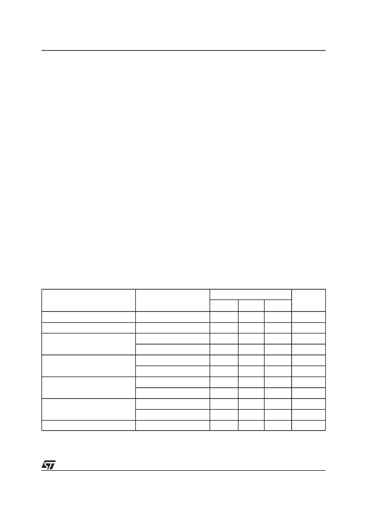
Table 13. Program, Erase Times and Program/Erase Endurance Cycles
(TA = 0 to 70°C or –40 to 85°C; VDD = 2.7V to 3.6V)
Parameter
Test Condition s
M28W320C
Min
Typ (1)
Max
Word Program
VPP = VDD
10
200
Double Word Program
VPP = 12V ±5%
10
200
Main Block Program
VPP = 12V ±5%
VPP = VDD
0.16
5
0.32
5
Parameter Block Program
VPP = 12V ±5%
VPP = VDD
0.02
4
0.04
4
Main Block Erase
VPP = 12V ±5%
VPP = VDD
1
10
1
10
Parameter Block Erase
VPP = 12V ±5%
VPP = VDD
0.8
10
0.8
10
Program/Erase Cycles (per Block)
Note: TA = 25 °C.
100,000
Unit
µs
µs
sec
sec
sec
sec
sec
sec
sec
sec
cycles
13/42
Share Link: 