ICL7109 Ver la hoja de datos (PDF) - Intersil
Número de pieza
componentes Descripción
Fabricante
ICL7109 Datasheet PDF : 25 Pages
| |||
ICL7109
such that 2048 clock periods is close to an integral multiple of the 60Hz period (but should not be less than 50pF).
INTEGRATOR
OUTPUT
INTERNAL
CLOCK
INTERNAL
LATCH
STATUS
OUTPUT
MODE
INPUT
UART
INTERNAL NORM
MODE
SEND INPUT
(UART TBRE)
CE/LOAD OUTPUT
(UART TBRL)
HBEN
ZERO CROSSING
OCCURS
ZERO CROSSING
DETECTED
SEND
SENSED
SEND
SENSED
TERMINATES
UART MODE
HIGH BYTE
DATA
LBEN
DATA VALID
LOW BYTE
DATA
DATA VALID
= DON’T CARE
= THREE-STATE HIGH IMPEDANCE
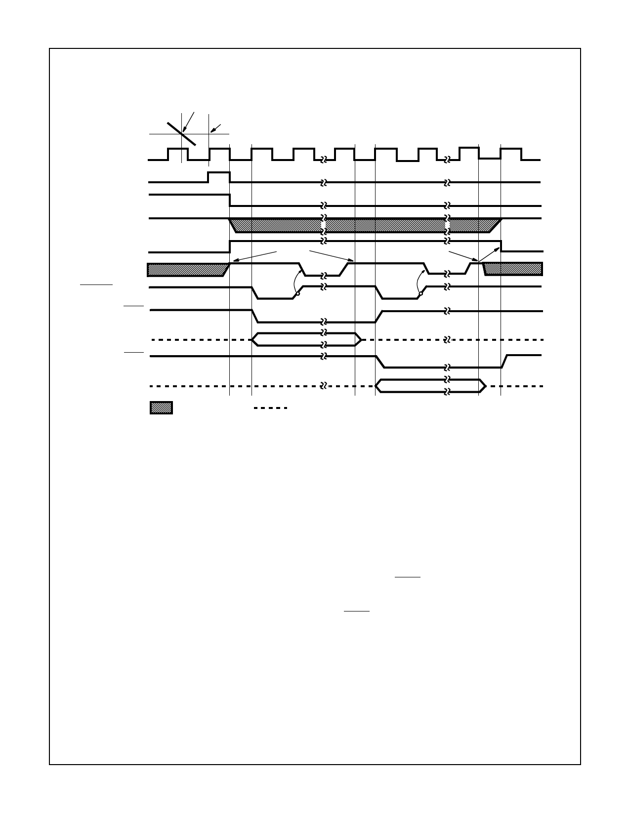
FIGURE 8. HANDSHAKE - TYPICAL UART INTERFACE TIMING
When the OSCILLATOR SELECT input is low a feedback
device and output and input capacitors are added to the oscil-
lator. In this configuration, as shown in Figure 11, the oscilla-
tor will operate with most crystals in the 1MHz to 5MHz range
with no external components. Taking the OSCILLATOR
SELECT input low also inserts a fixed ÷58 divider circuit
between the BUFFERED OSCILLATOR OUTPUT and the
internal clock. Using an inexpensive 3.58MHz TV crystal, this
division ratio provides an integration time given by:
tINT = (2048 clock periods) x (tCLOCK) = 33.18ms where:
tCLOCK = 3----.--5---8-5---M-8----H-----Z--
This time is very close to two 60Hz periods or 33ms. The
error is less than one percent, which will give better than
40dB 60Hz rejection. The converter will operate reliably at
conversion rates of up to 30 per second, which corresponds
to a clock frequency of 245.8kHz.
If at any time the oscillator is to be overdriven, the overdriv-
ing signal should be applied at the OSCILLATOR INPUT,
and the OSCILLATOR OUTPUT should be left open. The
internal clock will be of the same frequency, duty cycle, and
phase as the input signal when OSCILLATOR SELECT is
left open. When OSCILLATOR SELECT is at GND, the clock
will be a factor of 58 below the input frequency.
possible to use one 3.58MHz crystal for both devices. The
BUFFERED OSCILLATOR OUTPUT of the ICL7109 may be
used to drive the OSCILLATOR INPUT of the UART, saving
the need for a second crystal. However, the BUFFERED
OSCILLATOR OUTPUT does not have a great deal of drive
capability, and when driving more than one slave device
external buffering should be used.
Test Input
When the TEST input is taken to a level halfway between V+
and GND, the counter output latches are enabled, allowing
the counter contents to be examined anytime.
When the RUN/HOLD is low and the TEST input is
connected to GND, the counter outputs are all forced into the
high state, and the internal clock is disabled. When the
RUN/HOLD returns high and the TEST input returns to the
1/2 (V+ - GND) voltage (or to V+) and one clock is applied,
all the counter outputs will be clocked to the low state. This
allows easy testing of the counter and its outputs.
When using the ICL7109 with the IM6403 UART, it is
16
Share Link: 