RT9206 Ver la hoja de datos (PDF) - Richtek Technology
Número de pieza
componentes Descripción
Fabricante
RT9206 Datasheet PDF : 21 Pages
| |||
RT9206
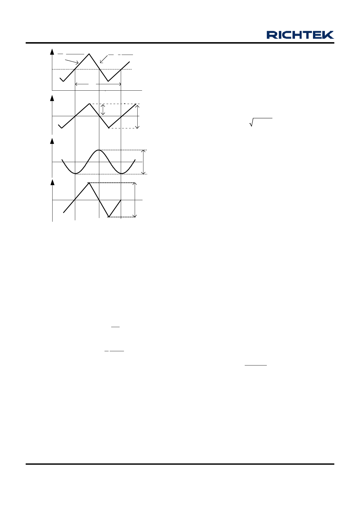
iL
diL= VIN-VOUT
dt
L
d iL
VOUT
dt =
L
IO
TS
ic
1/2ΔIL
0
ΔIL
VOC
VOR
0
ΔVOC
ΔIL x rc
t1
t2
Figure 2. The related waveforms of output capacitor.
The AC impedance of output capacitor at operating
frequency is quite smaller than the load impedance, so
the ripple current ( ∆IL) of the inductor current flows mainly
through output capacitor. The output ripple voltage is
described as :
ΔVOUT = ΔVOR + ΔVOC
(2)
ΔVOUT
=
ΔIL
× rC
+
1
Co
∫tt12 ic
dt
(3)
ΔVOUT
=
ΔIL
× rC +
1
8
VOUT
COL
(1- D)TS2
(4)
where ∆VOR is caused by ESR and ∆VOC by capacitance.
For electrolytic capacitor application, typically 90~95% of
the output voltage ripple is contributed by the ESR of output
capacitor. So Equation (4) could be simplified as :
ΔVOUT = ΔIL × rC
(5)
Users could connect capacitors in parallel to get calculated
ESR.
Input Capacitor Selection
The selection of input capacitor is mainly based on its
maximum ripple current capability. The buck converter
draws pulsewise current from the input capacitor during
the on time of S1 as shown in Figure 1. The RMS value of
ripple current flowing through the input capacitor is
described as :
Irms = IO D(1- D)
(A)
(6)
The input capacitor must be cable of handling this ripple
current. Sometime, for higher efficiency the low ESR
capacitor is necessarily.
Power MOSFET Selection
The selection of MOSFETs is based on consideration of
maximum gate-source voltage (Vgs), drain-source voltage
(Vdss), maximum drain current (Id), drain-source on-state
resistance Rds(on) and thermal management. The MOSFETs
are driven by VINT that is internally regulated as 6.0V. Low
threshold voltage MOSFET should be selected to guarantee
that it could fully turn on at Vgs = 6.0V.
The total power dissipation of external MOSFETs consists
of conduction and switching losses. The conduction losses
of high-side and low-side MOSFETs are described by
equation (7) and (8), respectively.
(High-side MOSFET)
PH - con = I02 × D × Rds(on) ×θ r (W)
(7)
(Low-side MOSFET)
PL - con = I02 × (1- D)×Rds(on) ×θ r (W)
(8)
Where
θ r is temperature dependency of Rds(on)
The total switching loss is approximated as.
Vds(off)
Psw = IOUT ×
× (tr + tf) × fs (W) (9)
2
Where
Vds(off) is voltage from drain to source at MOSFET
off time.
tr and tf are rise-time and fall-time, respectively.
IOUT= Load current
fs= Switching frequency
www.richtek.com
14
DS9206-11 March 2007
Share Link: 