NCP3020A Ver la hoja de datos (PDF) - ON Semiconductor
Número de pieza
componentes Descripción
Fabricante
NCP3020A Datasheet PDF : 23 Pages
| |||
NCP3020A, NCP3020B, NCV3020A, NCV3020B
18
17
16
15
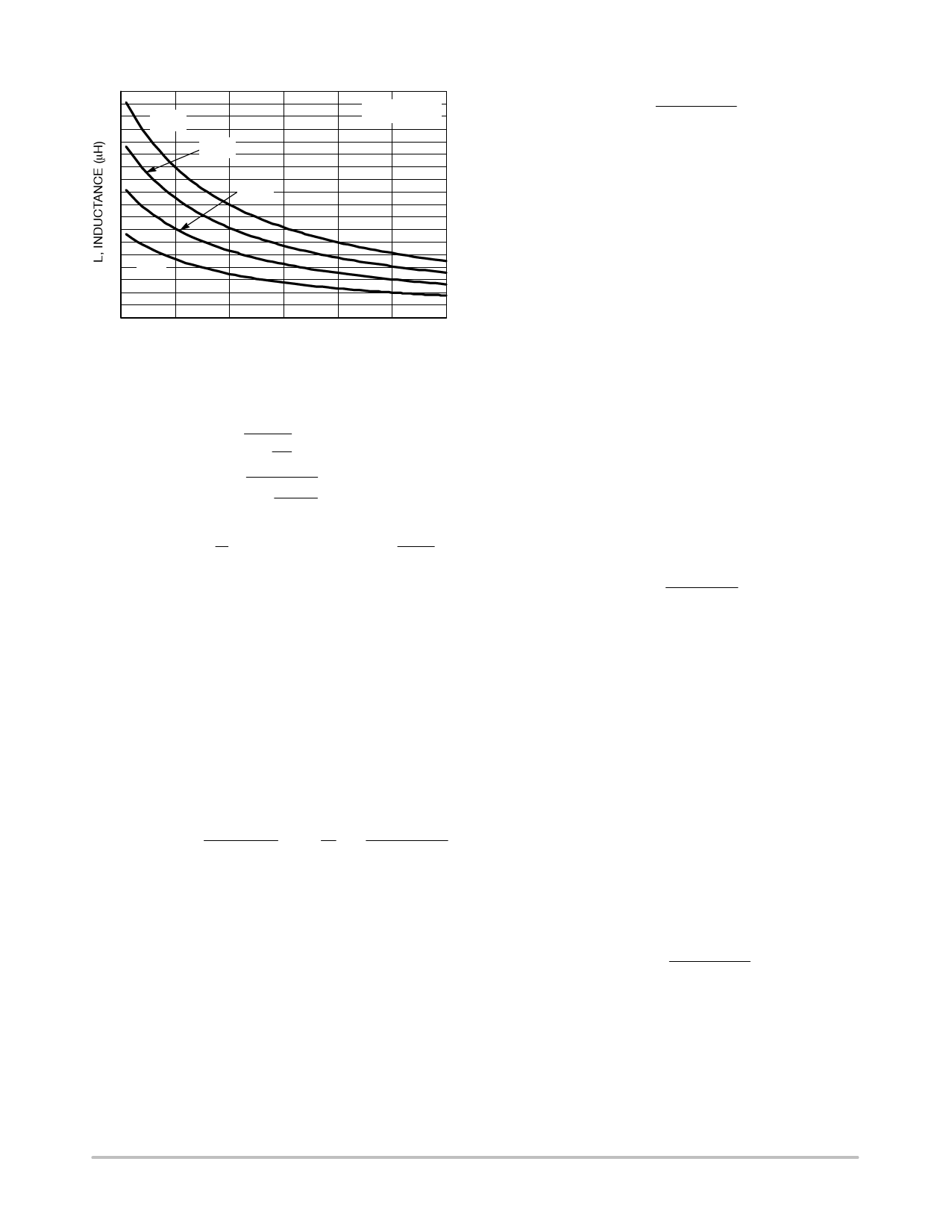
18 V
14
13
12
11
10
9
8
7
6
5
4
3
9V
2
1
0
10%
15%
15 V
12 V
20% 25%
Vout = 3.3 V
30% 35% 40%
VIN, (V)
Figure 32. Ripple Current Ratio vs. Inductance
To keep within the bounds of the parts maximum rating,
calculate the RMS current and peak current.
Ǹ IRMS + IOUT @
1 ) ra2 ³ 10.02 A
12
Ǹ + 10 A @ 1 ) (0.24)2
12
(eq. 8)
ǒ Ǔ ǒ Ǔ IPK + IOUT @
1 ) ra
2
³ 11.2 A + 10 A @
(0.24)
1)
2
(eq. 9)
An inductor for this example would be around 3.3 mH and
should support an rms current of 10.02 A and a peak current
of 11.2 A.
The final selection of an output inductor has both
mechanical and electrical considerations. From a
mechanical perspective, smaller inductor values generally
correspond to smaller physical size. Since the inductor is
often one of the largest components in the regulation system,
a minimum inductor value is particularly important in
space−constrained applications. From an electrical
perspective, the maximum current slew rate through the
output inductor for a buck regulator is given by Equation 10.
SlewRateLOUT
+
VIN * VOUT
LOUT
³
2.6
A
ms
12 V * 3.3 V
+
3.3 mH
(eq. 10)
This equation implies that larger inductor values limit the
regulator’s ability to slew current through the output
inductor in response to output load transients. Consequently,
output capacitors must supply the load current until the
inductor current reaches the output load current level. This
results in larger values of output capacitance to maintain
tight output voltage regulation. In contrast, smaller values of
inductance increase the regulator’s maximum achievable
slew rate and decrease the necessary capacitance, at the
expense of higher ripple current. The peak−to−peak ripple
current for the NCP3020A is given by the following
equation:
IPP
+
VOUT(1
LOUT @
* D)
FSW
(eq. 11)
Ipp is the peak to peak current of the inductor. From this
equation it is clear that the ripple current increases as LOUT
decreases, emphasizing the trade−off between dynamic
response and ripple current.
The power dissipation of an inductor consists of both
copper and core losses. The copper losses can be further
categorized into dc losses and ac losses. A good first order
approximation of the inductor losses can be made using the
DC resistance as they usually contribute to 90% of the losses
of the inductor shown below:
LPCU + IRMS 2 @ DCR
(eq. 12)
The core losses and ac copper losses will depend on the
geometry of the selected core, core material, and wire used.
Most vendors will provide the appropriate information to
make accurate calculations of the power dissipation then the
total inductor losses can be capture buy the equation below:
LPtot + LPCU_DC ) LPCU_AC ) LPCore (eq. 13)
Input Capacitor Selection
The input capacitor has to sustain the ripple current
produced during the on time of the upper MOSFET, so it
must have a low ESR to minimize the losses. The RMS value
of this ripple is:
IinRMS + IOUT @ ǸD @ (1 * D)
(eq. 14)
D is the duty cycle, IinRMS is the input RMS current, and
IOUT is the load current.
The equation reaches its maximum value with D = 0.5.
Loss in the input capacitors can be calculated with the
following equation:
PCIN + ESRCIN @ ǒIIN*RMSǓ2
(eq. 15)
PCIN is the power loss in the input capacitors and ESRCIN
is the effective series resistance of the input capacitance.
Due to large dI/dt through the input capacitors, electrolytic
or ceramics should be used. If a tantalum must be used, it
must by surge protected. Otherwise, capacitor failure could
occur.
Input Start−up Current
To calculate the input startup current, the following
equation can be used.
IINRUSH
+
COUT @ VOUT
tSS
(eq. 16)
Iinrush is the input current during startup, COUT is the total
output capacitance, VOUT is the desired output voltage, and
tSS is the soft start interval. If the inrush current is higher than
the steady state input current during max load, then the input
fuse should be rated accordingly, if one is used.
http://onsemi.com
17
Share Link: 