L6226Q Ver la hoja de datos (PDF) - STMicroelectronics
Número de pieza
componentes Descripción
Fabricante
L6226Q Datasheet PDF : 29 Pages
| |||
L6226Q
Circuit description
4.2
Logic inputs
Pins IN1A, IN2A, IN1B, IN2B, ENA and ENB are TTL/CMOS and microcontroller compatible
logic inputs. The internal structure is shown in Figure 6. Typical value for turn-on and turn-off
thresholds are respectively Vthon = 1.8 V and Vthoff = 1.3 V.
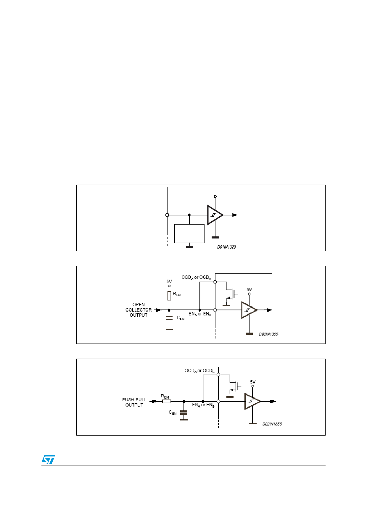
Pins ENA and ENB are commonly used to implement overcurrent and thermal protection by
connecting them respectively to the outputs OCDA and OCDB, which are open-drain
outputs. If that type of connection is chosen, some care needs to be taken in driving these
pins. Two configurations are shown in Figure 7 and Figure 8. If driven by an open drain
(collector) structure, a pull-up resistor REN and a capacitor CEN are connected as shown in
Figure 7. If the driver is a standard push-pull structure the resistor REN and the capacitor
CEN are connected as shown in Figure 8. The resistor REN should be chosen in the range
from 2.2 kΩ to 180 kΩ. Recommended values for REN and CEN are respectively 100 kΩ and
5.6 nF. More information on selecting the values is found in the overcurrent protection
section.
Figure 6. Logic inputs internal structure
9
(6'
3527(&7,21
',1
Figure 7. ENA and ENB pins open collector driving
Figure 8. ENA and ENB pins push-pull driving
Doc ID 14335 Rev 5
11/29
Share Link: 