MAX3421EEHJ(2006) Ver la hoja de datos (PDF) - Maxim Integrated
Número de pieza
componentes Descripción
Fabricante
MAX3421EEHJ Datasheet PDF : 29 Pages
| |||
USB Peripheral/Host Controller
with SPI Interface
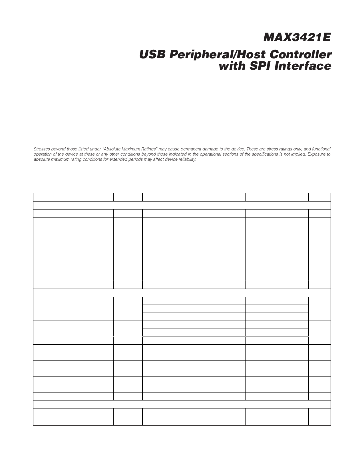
ABSOLUTE MAXIMUM RATINGS
(All voltages referenced to GND, unless otherwise noted.)
VCC ......................................................................... -0.3V to +4V
VL .............................................................................-0.3V to +4V
VBCOMP .................................................................-0.3V to +6V
D+, D-, XI, XO ............................................-0.3V to (VCC + 0.3V)
SCLK, MOSI, MISO, SS, RES, GPOUT7–GPOUT0,
GPIN7–GPIN0, GPX, INT ..........................-0.3V to (VL + 0.3V)
Continuous Power Dissipation (TA = +70°C)
32-Pin TQFN (derate 21.3mW/°C above +70°C) .......1702mW
32-Pin TQFP (derate 13.1mW/°C above +70°C)........1047mW
Operating Temperature Range ...........................-40°C to +85°C
Junction Temperature ......................................................+150°C
Storage Temperature Range .............................-65°C to +150°C
Lead Temperature (soldering, 10s) .................................+300°C
Stresses beyond those listed under “Absolute Maximum Ratings” may cause permanent damage to the device. These are stress ratings only, and functional
operation of the device at these or any other conditions beyond those indicated in the operational sections of the specifications is not implied. Exposure to
absolute maximum rating conditions for extended periods may affect device reliability.
ELECTRICAL CHARACTERISTICS
(VCC = +3V to +3.6V, VL = +1.4V to +3.6V, TA = TMIN to TMAX, unless otherwise noted. Typical values are at VCC = +3.3V, VL =
+2.5V, TA = +25°C.) (Note 3)
PARAMETER
DC CHARACTERISTICS
Supply Voltage VCC
Logic-Interface Voltage VL
SYMBOL
VCC
VL
CONDITIONS
MIN TYP MAX UNITS
3.0
3.3
3.6
V
1.4
3.6
V
VCC Supply Current
Continuously transmitting on D+ and D- at
ICC
12Mbps, CL = 50pF on D+ and D- to GND,
CONNECT = 0
45
mA
VL Supply Current
IL
SCLK toggling at 20MHz, SS = low,
GPIN7–GPIN0 = 0
2.35
10
mA
VCC Supply Current During Idle
ICCID D+ = high, D- = low
8.7
15
mA
VCC Suspend Supply Current
ICCSUS CONNECT = 0, PWRDOWN = 1 (Note 4)
0.031
5
mA
VL Suspend Supply Current
ILSUS CONNECT = 0, PWRDOWN = 1
20
50
µA
LOGIC-SIDE I/O
ILOAD = +1mA
VL - 0.4
MISO, GPOUT7–GPOUT0, GPX,
INT Output High Voltage
VOH ILOAD = +5mA, VL < 2.5V (Note 5)
VL - 0.45
V
ILOAD = +10mA, VL ≥ 2.5V (Note 5)
VL - 0.4
MISO, GPOUT7–GPOUT0, GPX,
INT Output Low Voltage
ILOAD = -1mA
VOL
ILOAD = -20mA, VL < 2.5V (Note 5)
ILOAD = -20mA, VL ≥ 2.5V (Note 5)
0.4
0.6
V
0.4
SCLK, MOSI, GPIN7–GPIN0, SS,
RES Input High Voltage
VIH
2/3 x VL
V
SCLK, MOSI, GPIN7–GPIN0, SS,
RES Input Low Voltage
VIL
0.4
V
SCLK, MOSI, SS, RES Input
Leakage Current
IIL
-1
+1
µA
GPIN7–GPIN0 Pullup Resistor to VL RGPIN
TRANSCEIVER SPECIFICATIONS
10
20
30
kΩ
Differential-Receiver Input
Sensitivity
|VD+ - VD-|
0.2
V
______________________________________________________________________________________ 11
Share Link: 