GT28F400B3B150 Ver la hoja de datos (PDF) - Intel
Número de pieza
componentes Descripción
Fabricante
GT28F400B3B150 Datasheet PDF : 49 Pages
| |||
E
SMART 3 ADVANCED BOOT BLOCK–WORD-WIDE
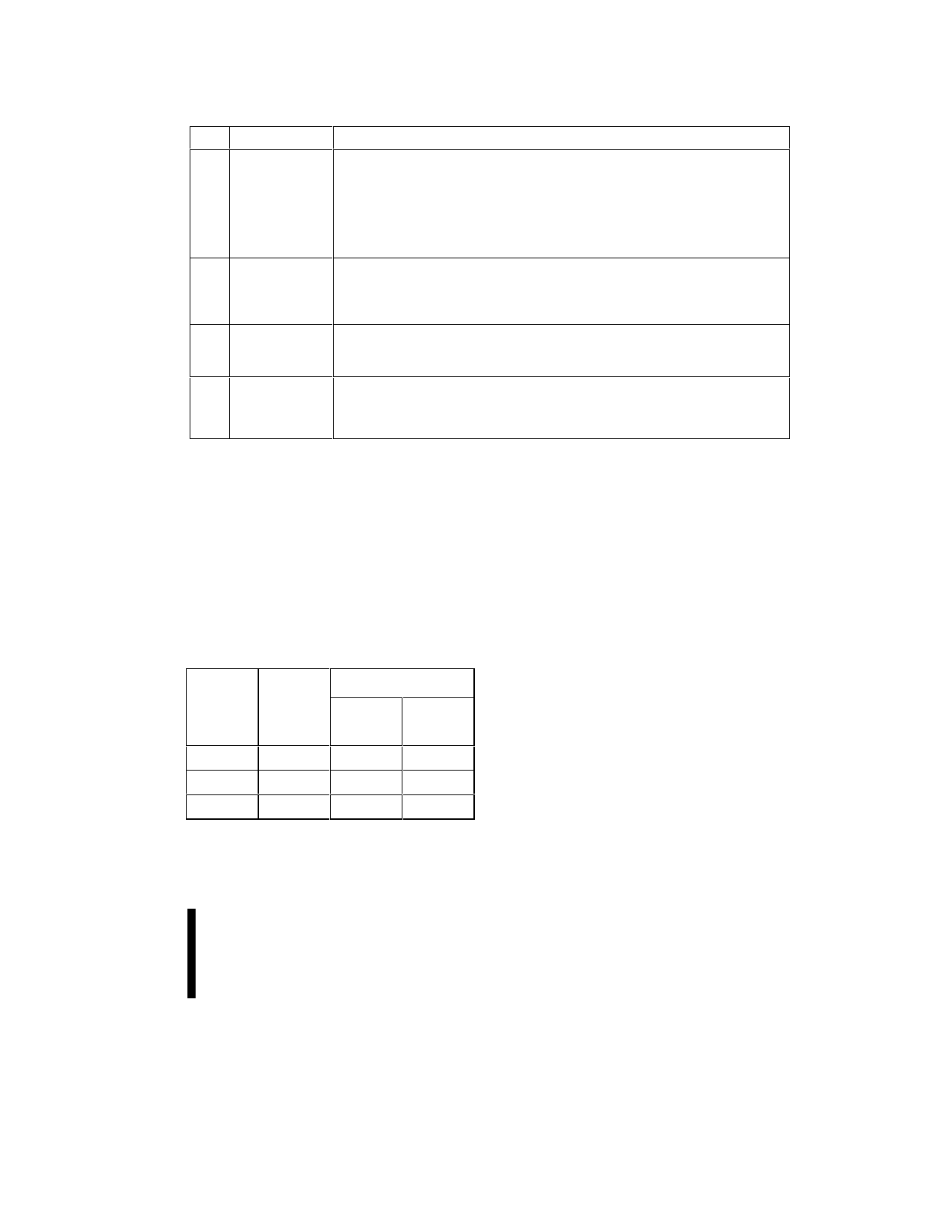
Table 4. Command Codes and Descriptions (Continued)
Code Device Mode
Description
B0
Program
Issuing this command will begin to suspend the currently executing
Suspend
program/erase operation. The status register will indicate when the operation
Erase
Suspend
has been successfully suspended by setting either the program suspend (SR.2)
or erase suspend (SR.6) and the WSM Status bit (SR.7) to a “1” (ready). The
WSM will continue to idle in the SUSPEND state, regardless of the state of all
input control pins except RP#, which will immediately shut down the WSM and
the remainder of the chip if it is driven to VIL. See Sections 3.2.4.1 and 3.2.5.1.
70 Read Status This command places the device into read status register mode. Reading the
Register
device will output the contents of the status register, regardless of the address
presented to the device. The device automatically enters this mode after a
program or erase operation has been initiated. See Section 3.2.3.
50 Clear Status The WSM can set the Block Lock Status (SR.1) , V PP Status (SR.3), Program
Register
Status (SR.4), and Erase Status (SR.5) bits in the status register to “1,” but it
cannot clear them to “0.” Issuing this command clears those bits to “0.”
90
Intelligent Puts the device into the intelligent identifier read mode, so that reading the
Identifier
device will output the manufacturer and device codes (A0 = 0 for manufacturer,
A0 = 1 for device, all other address inputs are ignored). See Section 3.2.2.
NOTE:
See Appendix B for mode transition information.
3.2.2
READ INTELLIGENT IDENTIFIER
To read the manufacturer and device codes, the
device must be in read intelligent identifier mode,
which can be reached by writing the Intelligent
Identifier command (90H). Once in intelligent
identifier mode, A0 = 0 outputs the manufacturer’s
identification code and A0 = 1 outputs the device
code. See Table 5 for product signatures. To return
to read array mode, write the Read Array command
(FFH).
Table 5. Intelligent Identifier Table
Size
4-Mbit
8-Mbit
16-Mbit
Mfr. ID
0089H
0089H
0089H
Device ID
-T
-B
(Top Boot) (Bottom
Boot)
8894H
8895H
8892H
8893H
8890H
8891H
3.2.3
READ STATUS REGISTER
The device status register indicates when a
program or erase operation is complete, and the
success or failure of that operation. To read the
status register issue the Read Status Register
(70H) command to the CUI. This causes all
subsequent read operations to output data from the
status register until another command is written to
the CUI. To return to reading from the array, issue
the Read Array (FFH) command.
The status register bits are output on DQ0–DQ7.
The upper byte, DQ8–DQ15, outputs 00H during a
Read Status Register command.
The contents of the status register are latched on
the falling edge of OE# or CE#. This prevents
possible bus errors which might occur if status
register contents change while being read. CE# or
OE# must be toggled with each subsequent status
read, or the status register will not indicate
completion of a program or erase operation.
PRELIMINARY
17
Share Link: 