ST70137 Ver la hoja de datos (PDF) - STMicroelectronics
Número de pieza
componentes Descripción
Fabricante
ST70137 Datasheet PDF : 22 Pages
| |||
ST70137
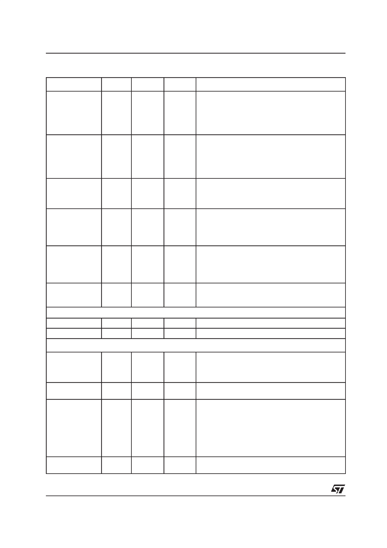
PIN DESCRIPTION (continued)
Signal Name Direction Init Status Polarity
Signal Description
PCI_TRDYN
I/O
I
PCI_PERRN
I/O
I
PCI_SERRN
PCI_INTAN
O
Z
O
Z
PCI_PMEN
O
Z
PCI_STOPN
I/O
I
USB INTERFACE
DPLUS
I/O
I
DMINUS
I/O
I
L
PCI Target Ready
This signal is driven by the select target to indicate the tar-
get is able to complete the current data phase. During
read transactions, it indicates PCI_AD[] contains valid
data. Wait states occur until both PCI_TRDYN and
PCI_IRDYN are asserted togheter.
L
PCI Parity Error
Only for reporting data parity errors for all bus transactions
except for special cycles. It is driven by the agent receiving
data two clock cycles after the parity was detected as an
error. This signal is driven inactive (high) for one clock
cycle prior to returning to the tri-state condition.
L
PCI System Error
Used to report address and data parity errors on special
cycle commands and any other error condition having a
catastrophic system impact.
L
PCI Interrupt A
This signal is defined as optional and level sensitive. Driv-
ing it low will interrupt to the host. The PCI_INTAN inter-
rupt is to be used for any single function device requiring
an interrupt capability.
L
PCI Power Management Event
This signal is used to indicate that a power management
event has been detected. The PCI_PMEN signal is asyn-
chronous with respect to the PCI clock; it is set (if
enabled) by the low to high transition of the ACTD signal.
L
PCI Stop
This signal indicates the current target is requesting the
master to stop the current transaction.
+
Differential positive USB data input/output.
-
Differential negative USB data input/output.
MISCELLANEOUS INTERFACE
GP IO[3: 0]
I/O
I
CFG_MEM_SEL
I
I
USB_PCIN_sel
I
I
VAUX_D / USB_SP
I
I
-
General Purpose I/O Bus
These signals are controlled by internal registers located
inside ADSL uP block. At the Power-up, Hardware or
Software Reset the input direction is chosen.
-
Select Internal [1] or External [0] PCI/USB configuration
memory.
-
Select PCI [0] or USB [1] Interface
Selecting USB interface and if all Test Pins are set to
default value, all the PCI Pads are deactivated. The
power supply for this section can be not provided. The
PCI section is frozen.
Selecting PCI interface the DMINUS and DPLUS has to be
set to the low level (reset mode). The PLL is in power down
and no any clock will be provided to the USB section.
-
VAUX Detect when USB_PCIN_sel = [0] or USB SELF
POWERED when USB_PCIN_sel = [1].
11/22
Share Link: 