UT1750AR12WCC Ver la hoja de datos (PDF) - Aeroflex UTMC
Número de pieza
componentes Descripción
Fabricante
UT1750AR12WCC Datasheet PDF : 56 Pages
| |||
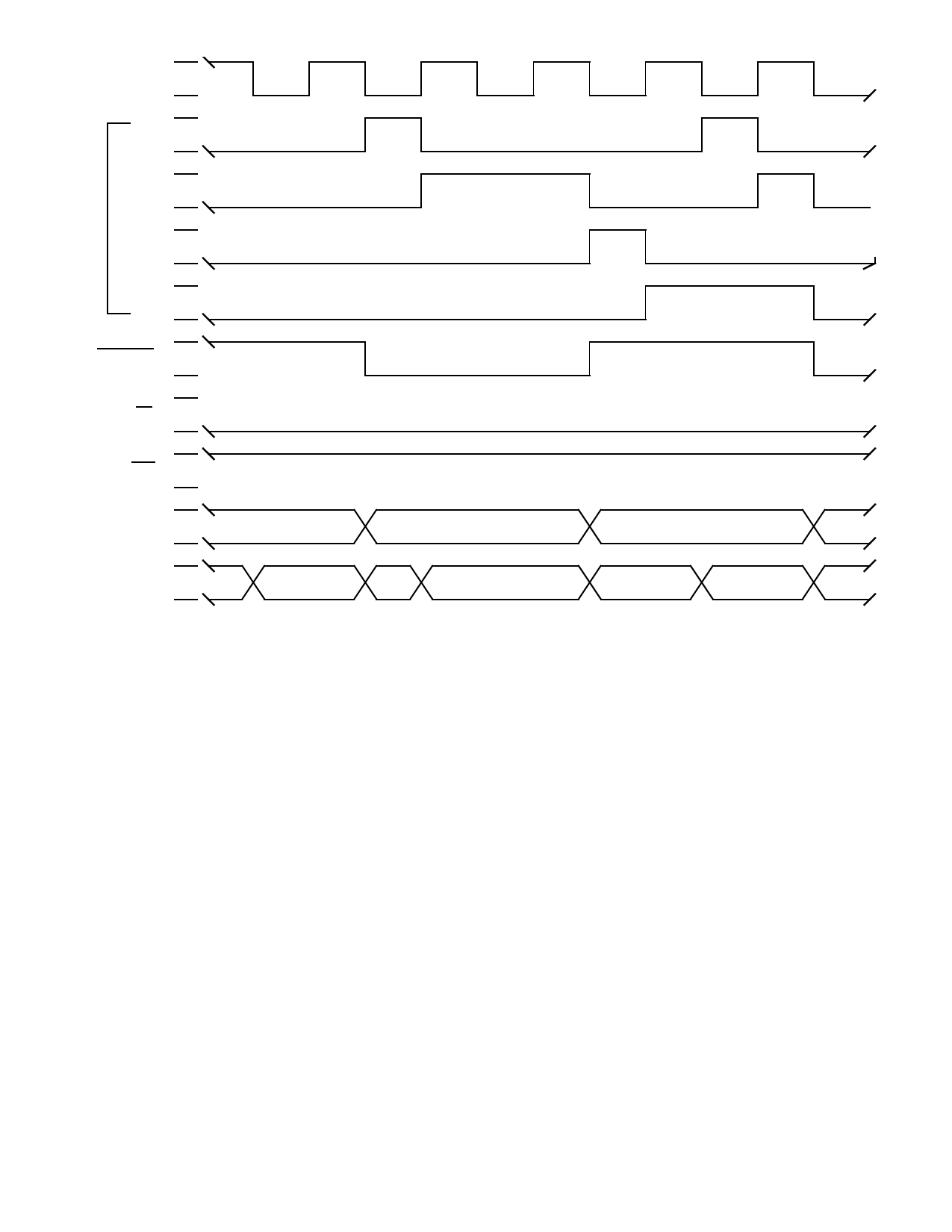
OSCIN
CK1
CK2
CK3
CK4
STATE1
OE
WE
RISC
ADDRESS
RISC
DATA
ADDRESS VALID (ACC)
ADDRESS VALID (IC)
DATA VALID
DATA VALID (RSn)
DATA VALID
Figure 29. LRI Instruction Typical Timing
INTERNAL UART OPERATION
The UT1750AR has an internal UART. Figure 30 (see page 30)
shows a diagram of the UT1750AR connected to a serial data
bus. The UART operates at a fixed frequency of 9600 baud with
eight data bits, one stop bit, and odd parity. The TIMCLK input
fixes the baud rate of the UART. This input also controls the
frequency of the internal 1750 timer registers (TA and TB).
The UART’s Transmitter Buffer Register (TXMT) and Receiver
Buffer Register (RCVR) are UT1750AR internal registers and
are treated as such when programming the UT1750AR. The
status of the UT1750AR’s internal UART is read from the
System Status Register (STATUS) bits 7 through 0.
UART Transmitter Operation
The transmitter portion of the UT1750AR’s UART is a double-
buffered configuration consisting of a Transmitter Register and
a Transmitter Buffer Register. The Transmitter Register contains
the serial data stream the UT1750AR is currently transmitting
through the UART; the Transmitter Buffer Register contains the
next message to transmit through the UART. The system
programmer reads the status of the Transmitter Register from
bit 1 (TE) of the STATUS and the status of the Transmitter Buffer
Register from bit 2 (TBE) of the STATUS. If bit 2 of the STATUS
is high, the UART transmitter is ready for data. Bit 1 is low
during the serial transmission and transitions to a high when a
transmission from the Transmitter Register is complete.
To initiate a serial data transmission, the system designer must
first load the data to transmit into the Transmitter Buffer Register
with the output instruction. This instruction loads the least
significant byte of the source register specified in the instruction
into the Transmitter Buffer Register. At this time, TBE goes low
and the UT1750AR automatically transfers the data word into
the Transmitter Register. After the transfer is complete, TE goes
low and TBE returns high indicating a serial transmission is
about to begin and the next data word can be loaded into the
Transmitter Buffer Register.
29
Share Link: 