ISL12023 Ver la hoja de datos (PDF) - Renesas Electronics
NГәmero de pieza
componentes DescripciГіn
Fabricante
ISL12023
Renesas Electronics

ISL12023 Datasheet PDF : 29 Pages
| |||
ISL12023
FOUT (Frequency Output)
This pin provides a clock signal which is related to the crystal
frequency. The output frequency is user selectable and enabled
via the I2C bus. It is an open drain output.
Serial Clock (SCL)
The SCL input is used to clock all serial data into and out of the
device. The input buffer on this pin is always active (not gated). It
is disabled when the backup power supply on the VBAT pin is
activated to minimize power consumption.
Serial Data (SDA)
SDA is a bi-directional pin used to transfer data into and out of
the device. It has an open drain output and may be ORed with
other open drain or open collector outputs. The input buffer is
always active (not gated) in normal mode.
An open drain output requires the use of a pull-up resistor. The
output circuitry controls the fall time of the output signal with the
use of a slope controlled pull-down. The circuit is designed for
400kHz I2C interface speeds. It is disabled when the backup
power supply on the VBAT pin is activated.
VDD, GND
Chip power supply and ground pins. The device will operate with
a power supply from VDD = 2.7V to 5.5VDC. A 0.1ВөF capacitor is
recommended on the VDD pin to ground. The VDD Negative and
VDD Positive Slew Rate specifications have to be observed.
LVRST (Low Voltage Reset)
This pin provides an interrupt signal output. This signal notifies a
host processor that the VDD level has dropped below the pre-
programmed level, normally 85% of nominal VDD. The brownout
trip level is programmable via a control register. It is an open
drain active low output.
Functional Description
Power Control Operation
The power control circuit accepts a VDD and a VBAT input. Many
types of batteries can be used with Intersil RTC products. For
example, 3.0V or 3.6V Lithium batteries are appropriate, and
battery sizes are available that can power the ISL12023 for up to
10 years. Another option is to use a super capacitor for
applications where VDD is interrupted for up to a month. See the
вҖңApplication SectionвҖқ on page 24 for more information.
Normal Mode (VDD) to Battery-Backup Mode
(VBAT)
To transition from the VDD to VBAT mode, both of the following
conditions must be met:
Condition 1:
VDD < VBAT - VBATHYS
where VBATHYS пӮ» 50mV
Condition 2:
VDD < VTRIP
where VTRIP пӮ» 2.2V
FN6682 Rev 3.00
December 6, 2011
Battery-Backup Mode (VBAT) to Normal Mode
(VDD)
The ISL12023 device will switch from the VBAT to VDD mode
when one of the following conditions occurs:
Condition 1:
VDD > VBAT + VBATHYS
where VBATHYS пӮ»пҖ 50mV
VDD
VBAT
VTRIP
BATTERY-BACKUP
MODE
3.0V
2.2V
VTRIP
VTRIP + VTRIPHYS
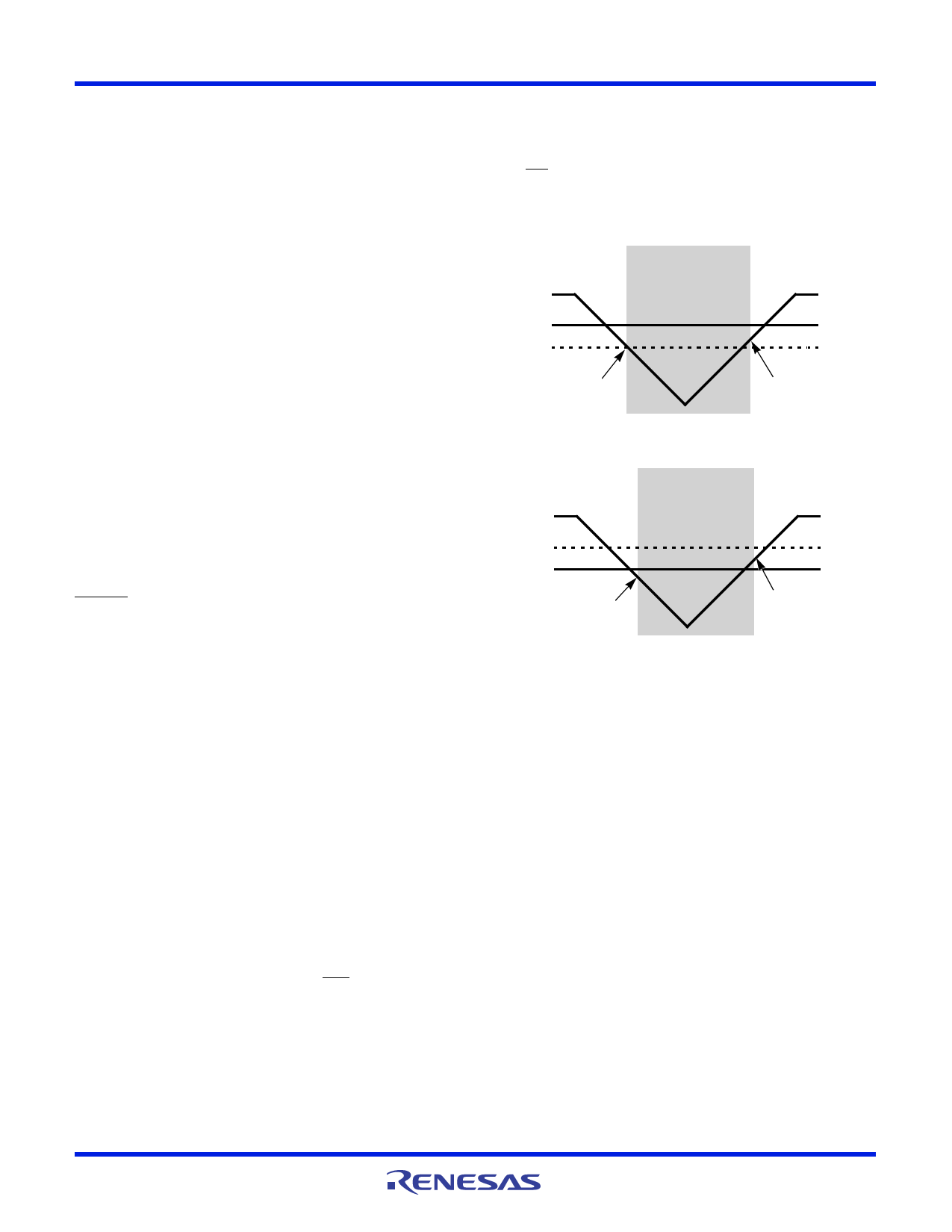
FIGURE 11. BATTERY SWITCHOVER WHEN VBAT > VTRIP
VDD
VTRIP
VBAT
VBAT - VBATHYS
BATTERY-BACKUP
MODE
2.2V
1.8V
VBAT + VBATHYS
FIGURE 12. BATTERY SWITCHOVER WHEN VBAT < VTRIP
Condition 2:
VDD > VTRIP + VTRIPHYS
where VTRIPHYS пӮ» 30mV
These power control situations are illustrated in Figures 11 and
12.
The I2C bus is deactivated in battery-backup mode to reduce
power consumption. Aside from this, all RTC functions are
operational during battery-backup mode. Except for SCL and SDA,
all the inputs and outputs of the ISL12023 are active during
battery-backup mode unless disabled via the control register.
The device Time Stamps the switchover from VDD to VBAT and
VBAT to VDD, and the time is stored in tSV2B and tSB2V registers
respectively. If multiple VDD power-down sequences occur before
status is read, the earliest VDD to VBAT power-down time is stored
and the most recent VBAT to VDD time is stored.
Temperature conversion and compensation can be enabled in
battery-backup mode. Bit BTSE in the BETA register controls this
operation, as described in вҖңBETA Register (BETA)вҖқ on page 17.
Power Failure Detection
The ISL12023 provides a Real Time Clock Failure Bit (RTCF) to
detect total power failure. It allows users to determine if the
device has powered up after having lost all power to the device
(both VDD and VBAT).
Page 9 of 29
Share Link: