VDP3104B Ver la hoja de datos (PDF) - Micronas
Número de pieza
componentes Descripción
Fabricante
VDP3104B Datasheet PDF : 72 Pages
| |||
PRELIMINARY DATA SHEET
VDP 31xxB
2.3.2. Demodulator
The entire signal (which might still contain luma) is now
quadrature-mixed to the baseband. The mixing frequen-
cy is equal to the subcarrier for PAL and NTSC, thus
achieving the chroma demodulation. For SECAM, the
mixing frequency is 4.286 MHz giving the quadrature
baseband components of the FM modulated chroma.
After the mixer, a lowpass filter selects the chroma com-
ponents; a downsampling stage converts the color dif-
ference signals to a multiplexed half rate data stream.
The subcarrier frequency in the demodulator is gener-
ated by direct digital synthesis; therefore, substandards
such as PAL 3.58 or NTSC 4.43 can also be demodu-
lated.
2.3.3. Chrominance Filter
The demodulation is followed by a lowpass filter for the
color difference signals for PAL/NTSC. SECAM requires
a modified lowpass function with bell-filter characteristic.
At the output of the lowpass filter, all luma information is
eliminated.
The lowpass filters are calculated in time multiplex for
the two color signals. Three bandwidth settings (narrow,
normal, broad) are available for each standard. For PAL/
NTSC, a wide band chroma filter can be selected. This
filter is intended for high bandwidth chroma signals, e.g.
a nonstandard wide bandwidth S-VHS signal.
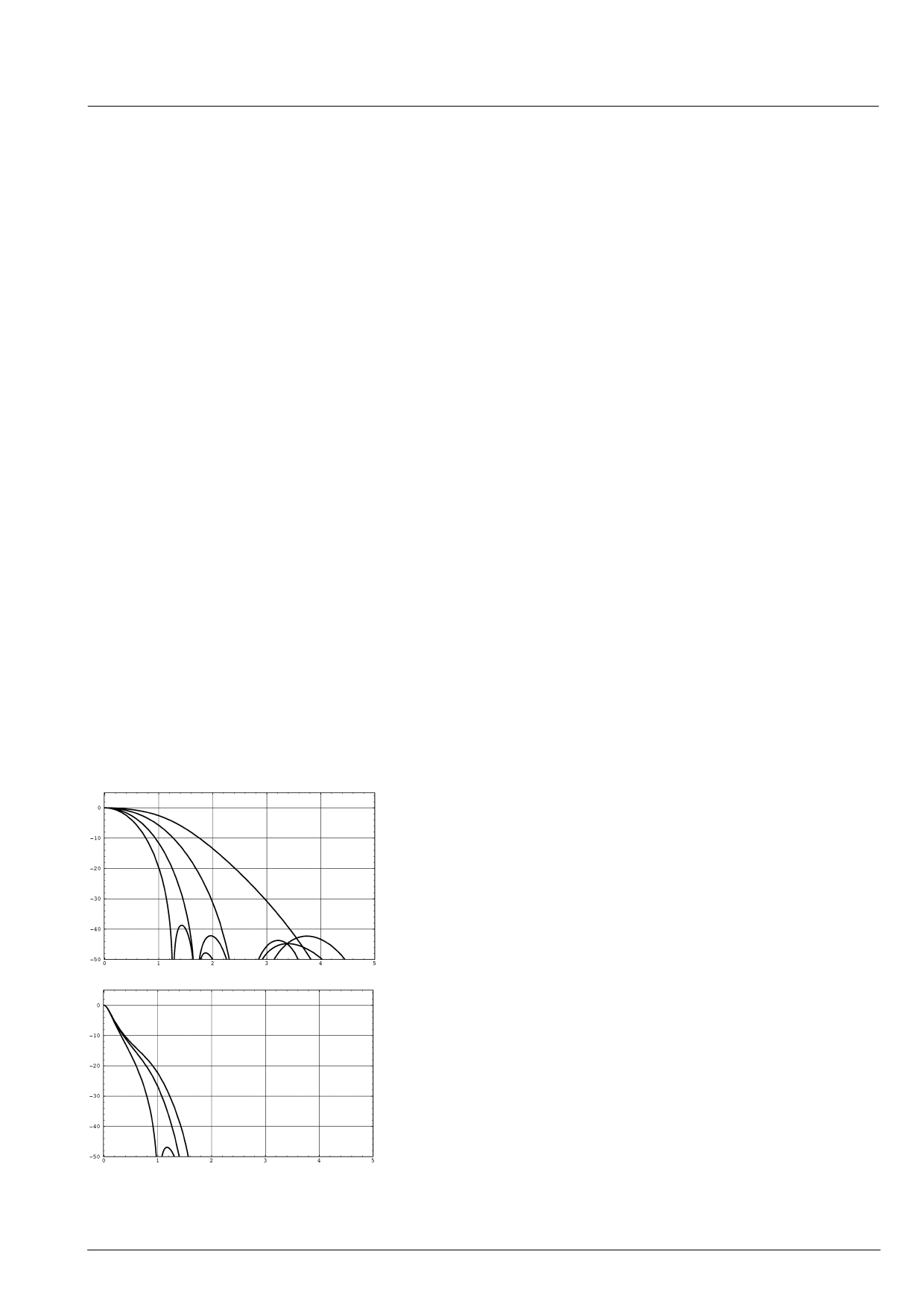
PAL/NTSC
SECAM
Fig. 2–6: Frequency response of chroma filters
Micronas
2.3.4. Frequency Demodulator
The frequency demodulator for demodulating the SE-
CAM signal is implemented as a CORDIC-structure. It
calculates the phase and magnitude of the quadrature
components by coordinate rotation.
The phase output of the CORDIC processor is differen-
tiated to obtain the demodulated frequency. After the
deemphasis filter, the Dr and Db signals are scaled to
standard CrCb amplitudes and fed to the crossover-
switch.
2.3.5. Burst Detection
In the PAL/NTSC-system the burst is the reference for
the color signal. The phase and magnitude outputs of
the CORDIC are gated with the color key and used for
controlling the phase-lock-loop (APC) of the demodula-
tor and the automatic color control (ACC) in PAL/NTSC.
The ACC has a control range of +30 ... –6 dB.
For SECAM decoding, the frequency of the burst is mea-
sured. Thus, the current chroma carrier frequency can
be identified and is used to control the SECAM proces-
sing. The burst measurements also control the color kill-
er operation; they can be used for automatic standard
detection as well.
2.3.6. Color Killer Operation
The color killer uses the burst-phase / burst-frequency
measurement to identify a PAL/NTSC or SECAM color
signal. For PAL/NTSC, the color is switched off (killed)
as long as the color subcarrier PLL is not locked. For SE-
CAM, the killer is controlled by the toggle of the burst fre-
quency. The burst amplitude measurement is used to
switch-off the color if the burst amplitude is below a pro-
grammable threshold. Thus, color will be killed for very
noisy signals. The color amplitude killer has a program-
mable hysteresis.
2.3.7. PAL Compensation / 1-H Comb Filter
The color decoder uses one fully integrated delay line.
Only active video is stored.
The delay line application depends on the color stan-
dard:
– NTSC: 1-H comb filter or color compensation
– PAL: color compensation
– SECAM: crossover-switch
In the NTSC compensated mode, Fig. 2–7 c), the color
signal is averaged for two adjacent lines. Thus, cross-
color distortion and chroma noise is reduced. In the
NTSC combfilter mode, Fig. 2–7 d), the delay line is in
the composite signal path, thus allowing reduction of
11
Share Link: 