XWM8721EDS Ver la hoja de datos (PDF) - Wolfson Microelectronics plc
Número de pieza
componentes Descripción
Fabricante
XWM8721EDS Datasheet PDF : 37 Pages
| |||
Production Data
WM8721 / WM8721L
Notes:
1. Ratio of output level with 1kHz full scale input, to the output level with all zeros into the digital input, measured ‘A’
weighted over a 20Hz to 20kHz bandwidth.
2. All performance measurements done with 20kHz low pass filter, and where noted an A-weight filter. Failure to use
such a filter will result in higher THD+N and lower SNR and Dynamic Range readings than are found in the Electrical
Characteristics. The low pass filter removes out of band noise; although it is not audible it may affect dynamic
specification values.
3. VMID decoupled with 10uF and 0.1uF capacitors (smaller values may result in reduced performance).
TERMINOLOGY
1. Signal-to-noise ratio (dB) - SNR is a measure of the difference in level between the full scale output and the output
with no signal applied. (No Auto-zero or Automute function is employed in achieving these results).
2. Dynamic range (dB) - DR is a measure of the difference between the highest and lowest portions of a signal.
Normally a THD+N measurement at 60dB below full scale. The measured signal is then corrected by adding the 60dB
to it. (e.g. THD+N @ -60dB= -32dB, DR= 92dB).
3. THD+N (dB) - THD+N is a ratio of the rms values of (Noise + Distortion)/Signal.
4. Stop band attenuation (dB) - Is the degree to which the frequency spectrum is attenuated (outside audio band).
5. Channel Separation (dB) - Also known as Cross-Talk. This is a measure of the amount one channel is isolated from
the other. Normally measured by sending a full scale signal down one channel and measuring the other.
6. Pass-Band Ripple - Any variation of the frequency response in the pass-band region.
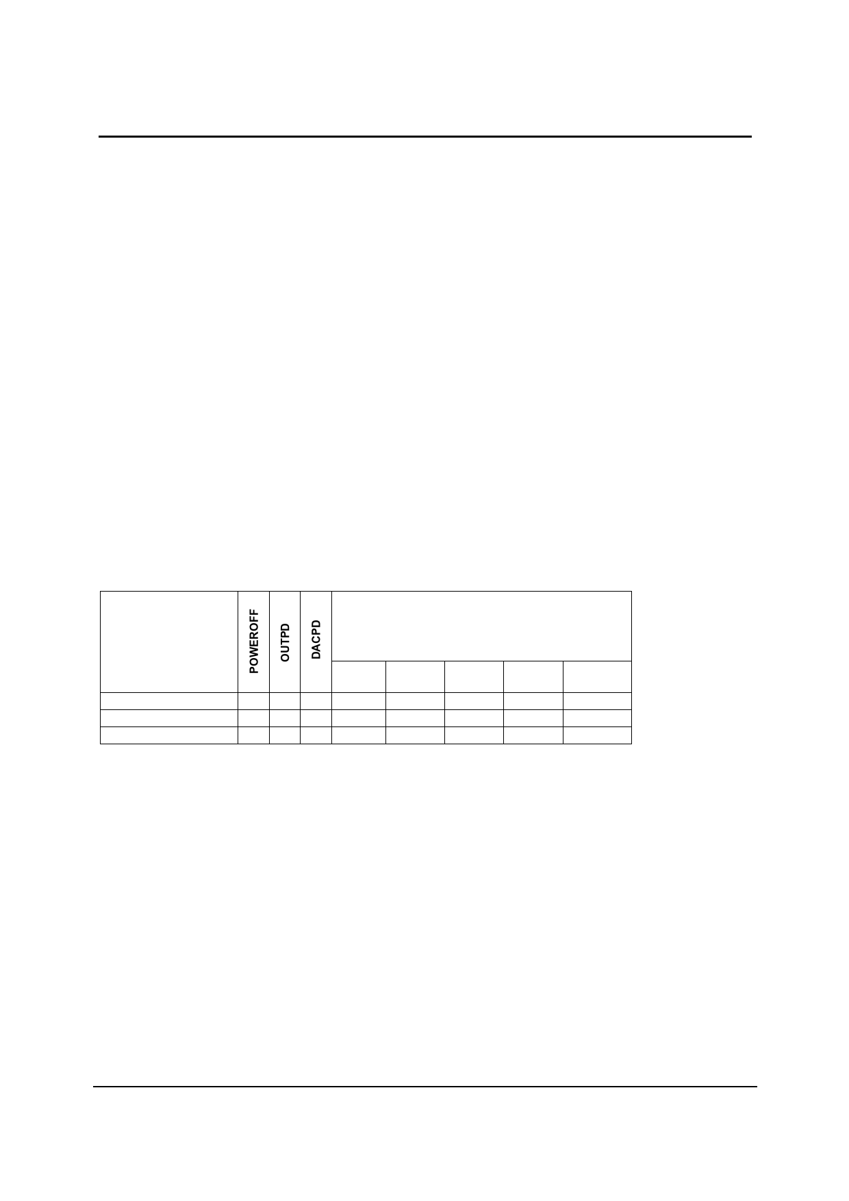
POWER CONSUMPTION
MODE DESCRIPTION
CURRENT CONSUMPTION
DAC Playback
Standby
Power Down
AVDD HPVDD
(3.3V) (3.3V)
000
3.5
1.7
011
17
0.4
111
0.4
0.3
Table 1 Powerdown Mode Current Consumption Examples
DCVDD
(1.5V)
1.3
0.7
0.7
DBVDD
(3.3V)
0.1
0.2
0.1
Notes:
1. TA = +25oC. Slave Mode, fs = 48kHz, MCLK = 256fs (12.288MHz).
2. All figures are quiescent, with no signal.
3. The power dissipation in the headphone itself not included in the above table.
UNITS
mA
µA
µA
w
PD Rev 4.0 November 2004
7
Share Link: 