TSL2580 Ver la hoja de datos (PDF) - TEXAS ADVANCED OPTOELECTRONIC SOLUTIONS
Número de pieza
componentes Descripción
Fabricante
TSL2580 Datasheet PDF : 34 Pages
| |||
TSL2580, TSL2581
LIGHT-TO-DIGITAL CONVERTER
1
7
11
8
1
S Slave Address Wr A Command Code A
8
1
Byte Count = N A
8
Data Byte 1
TAOS098 − MARCH 2010
1
A ...
8
Data Byte 2
1
A ...
8
Data Byte N
11
AP
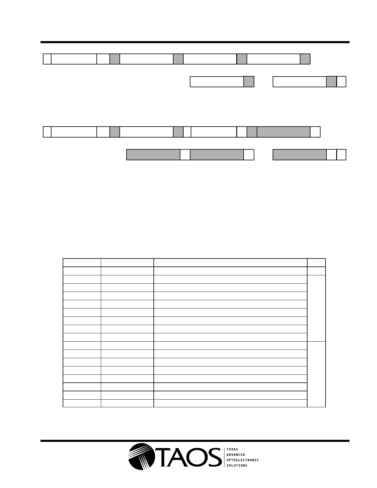
Figure 13. SMBus Block Write or I2C Write Protocols
NOTE: The I2C write protocol does not use the Byte Count packet, and the Master will continue sending Data Bytes until the Master initiates a
Stop condition. See the Command Register on page 12 for additional information regarding the Block Read/Write protocol.
1
7
11
S Slave Address Wr A
8
Command Code
11
7
11
A Sr Slave Address Rd A
8
Byte Count = N
1
A ...
8
1
Data Byte 1
A
8
Data Byte 2
1
A ...
8
Data Byte N
11
AP
1
Figure 14. SMBus Block Read or I2C Read (Combined Format) Protocols
NOTE: The I2C read protocol does not use the Byte Count packet, and the Master will continue receiving Data Bytes until the Master initiates
a Stop Condition. See the Command Register on page 13 for additional information regarding the Block Read/Write protocol.
Register Set
The TSL258x is controlled and monitored by sixteen registers and a command register accessed through the
serial interface. These registers provide for a variety of control functions and can be read to determine results
of the ADC conversions. The register set is summarized in Table 2.
Table 2. Register Address
ADDRESS
RESISTER NAME
REGISTER FUNCTION
R/W
−−
COMMAND
Specifies register address
W
00h
CONTROL
Control of basic functions
01h
TIMING
Integration time/gain control
02h
INTERRUPT
Interrupt control
03h
THLLOW
Low byte of low interrupt threshold
R/W
04h
THLHIGH
High byte of low interrupt threshold
05h
THLLOW
Low byte of high interrupt threshold
06h
THLHIGH
High byte of high interrupt threshold
07h
ANALOG
Analog control register
12h
ID
Part number / Rev ID
13h
CONSTANT
Number 4 (for SMBus block reads)
14h
DATA0LOW
ADC channel 0 LOW data register
15h
DATA0HIGH
ADC channel 0 HIGH data register
R
16h
DATA1LOW
ADC channel 1 LOW data register
17h
DATA1HIGH
ADC channel 1 HIGH data register
18h
TIMERLOW
Manual integration timer LOW register
19h
TIMERHIGH
Manual integration timer HIGH register
The mechanics of accessing a specific register depends on the specific SMB protocol used. See the section
on SMBus protocols, above. In general, the COMMAND register is written first to specify the specific
control/status register for following read/write operations.
The LUMENOLOGY r Company
r
Copyright E 2010, TAOS Inc.
r
www.taosinc.com
11
Share Link: 