TEA1211 Ver la hoja de datos (PDF) - Philips Electronics
Número de pieza
componentes Descripción
Fabricante
TEA1211 Datasheet PDF : 23 Pages
| |||
Philips Semiconductors
High efficiency auto-up/down
DC/DC converter
Preliminary specification
TEA1211HN
handbook, full pagewidth
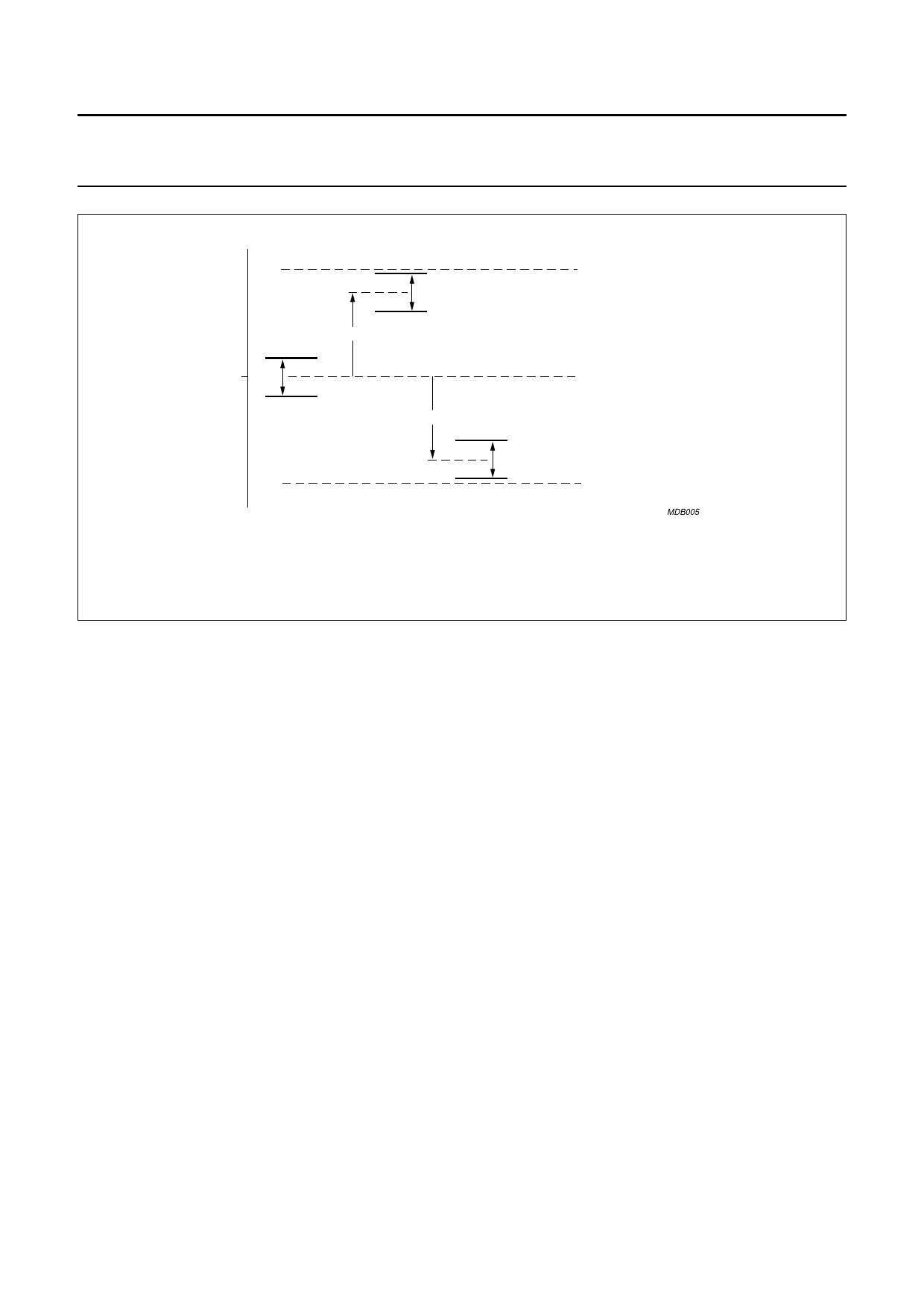
VOUT (typ.)
Vh = High window limit
Vl = Low window limit
Vh
2%
Vl
maximum positive spread of VFB
Vh
2%
Vl
+4%
upper specification limit
typical situation
−4%
Vh
2%
Vl
maximum negative spread of VFB
lower specification limit
MDB005
Fig.5 Spread of location of output voltage window.
7.2.3 SWITCHING SEQUENCE
Refer to Figures 1 and 3. In up-mode the cycle starts by
making P-down and N-up conducting in the first phase.
The second phase N-up opens and P-up starts
conducting. In down-mode the cycle starts with in the first
phase P-up and P-down conducting. The second phase
P-down opens and N-down starts conducting. In PFM
these two phases are followed by a third or wait phase that
opens all switches except for N-down, which is closed to
prevent the coil from floating.
The stationary mode or 4-phase cycle, which only occurs
in PFM, starts with in the first phase P-down and N-up
conducting. In the second phase P-down and P-up
conduct forming a short-cut from battery to output
capacitor. In the third phase P-up and N-down conduct.
The fourth or wait-phase again opens all switches except
for N-down which is closed to prevent the coil from floating.
7.3 Adjustable output voltage
The output voltage of the TEA1211HN can be set to a fixed
value by means of an external resistive divider. After
start-up through this divider, dynamic control of the output
voltage is made possible by use of an I2C-bus. The output
voltage can be programmed from 1.5 V to 5.5 V in
40 steps of 0.1 V each. In case of Power Amplifiers (PAs)
for example the output voltage of the TEA1211HN can be
adjusted to the output power to be transmitted by the PA,
in order to obtain maximum system efficiency.
7.4 Start-up
If the input voltage exceeds the start voltage, the
TEA1211HN starts ramping up the voltage at the output
capacitor. Ramping stops when the target level, set by the
external resistors, is reached.
7.5 Under voltage lockout
As a result of too high load or disconnection of the input
power source, the input voltage can drop too low to
guarantee normal regulation. In that case, the device
switches to a shut-down mode stopping the switching
completely. Start-up is possible by crossing the start-up
level again.
7.6 Shut-down
When pin SHDWN is made HIGH, the converter disables
all switches except for N-down (see Fig.1) and power
consumption is reduced to a few µA. N-down is kept
conducting to prevent the coil from floating.
7.7 Power switches
The power switches in the IC are two N-type and two
P-type MOSFETs, having a typical pin-to-pin resistance of
85 mΩ. The maximum continuous input/output current in
the switches is 1.7 A at 70 °C ambient temperature.
2003 Oct 13
7
Share Link: 