TEA1211 Ver la hoja de datos (PDF) - Philips Electronics
Número de pieza
componentes Descripción
Fabricante
TEA1211 Datasheet PDF : 23 Pages
| |||
Philips Semiconductors
High efficiency auto-up/down
DC/DC converter
Preliminary specification
TEA1211HN
7.2.1 PWM
PWM results in minimum AC currents in the circuit
components and hence optimum efficiency, cost and
EMC. In this mode the output voltage is allowed to vary
between two predefined voltage levels. When the output
voltage stays within this so called window, switching
continues in a fixed pattern. When the output voltage
reaches one of the window borders, the digital controller
immediately reacts by adjusting the duty cycle and
inserting a current step in such a way that the output
voltage stays within the window with higher or lower
current capability. This approach enables very fast
reaction to load variations.
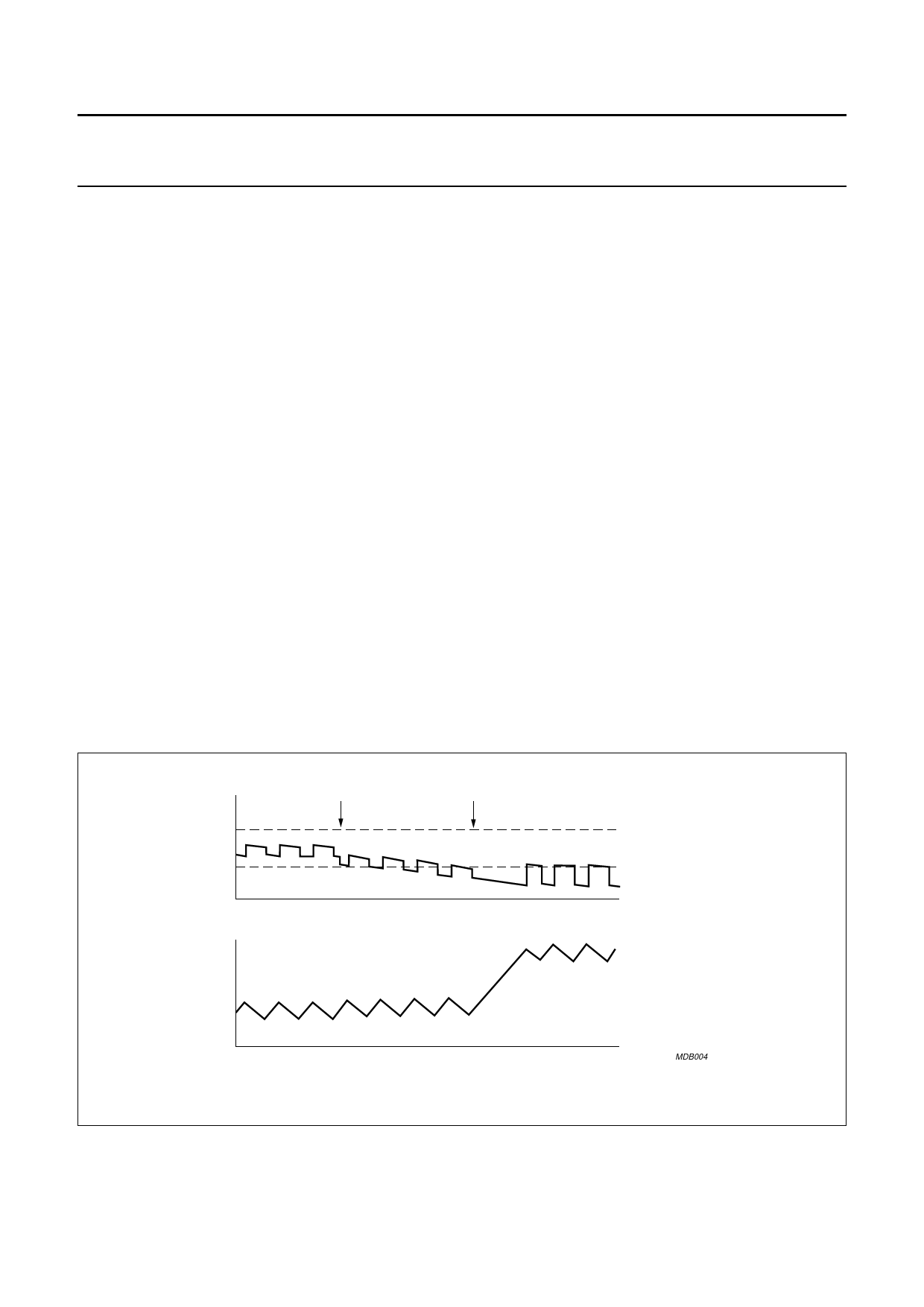
Figure 4 shows the TEA1211HN’s response to a sudden
load increase in case of up conversion. The upper trace
shows the output voltage. The ripple on top of the DC level
is a result of the current in the output capacitor, which
changes in sign twice per cycle, multiplied by the
capacitor’s internal Equivalent Series Resistance (ESR).
After each ramp-down of the inductor current, or when the
ESR effect increases the output voltage, the TEA1211HN
determines what to do in the next cycle. As soon as more
load current is taken from the output the output voltage
starts to decay. When the output voltage becomes lower
than the low limit of the window, corrective action is taken
by a ramp-up of the inductor current during a much longer
time. As a result, the DC current level is increased and
normal PWM control can continue. The output voltage
(including ESR effect) is again within the predefined
window.
Figure 5 depicts the spread of the output voltage window.
The absolute value is most dependent on spread, while the
actual window size is not affected. For one specific device,
the output voltage will not vary more than 2 % typically.
7.2.2 PFM
In low output power situations, TEA1211HN will switch
over to PFM mode operation in case PWM-only mode is
not activated. In this mode charge is transferred from
battery to output in single pulses with a wait phase in
between. Regulation information from earlier PWM mode
operation is used. This results in optimum inductor peak
current levels in PFM mode, which are slightly larger than
the inductor ripple current in PWM mode. As a result, the
transition between PFM and PWM mode is optimal under
all circumstances. In PFM mode, the TEA1211HN
regulates the output voltage to the limits shown in Fig.5.
Depending on the VIN to VOUT ratio the TEA1211HN
decides for a 3- or 4-phase cycle, where the last phase is
the wait phase. When the input voltage almost equals the
output voltage, one of the slopes of a 3-phase cycle
becomes weak. Then the charge, or the integral of its
pulse, is near to zero and no charge is transferred. In this
region the 4-phase cycle is used, (see Fig.3).
handbook, full pagewidth
VOUT
Iload
load increase
start corrective action
high window limit
low window limit
time
time
Fig.4 Response to load increase in up-mode.
MDB004
2003 Oct 13
6
Share Link: 