TEA1211 Ver la hoja de datos (PDF) - Philips Electronics
Número de pieza
componentes Descripción
Fabricante
TEA1211 Datasheet PDF : 23 Pages
| |||
Philips Semiconductors
High efficiency auto-up/down
DC/DC converter
handbook, halfpage
n.c. 8
GND 7
n.c. 6
GND 5
LXA 4
LXA 3
IN 2
LXA 1
TEA1211HN
17 n.c.
18 GND
19 n.c.
20 GND
21 LXB
22 LXB
23 OUT
24 LXB
MDB002
Preliminary specification
TEA1211HN
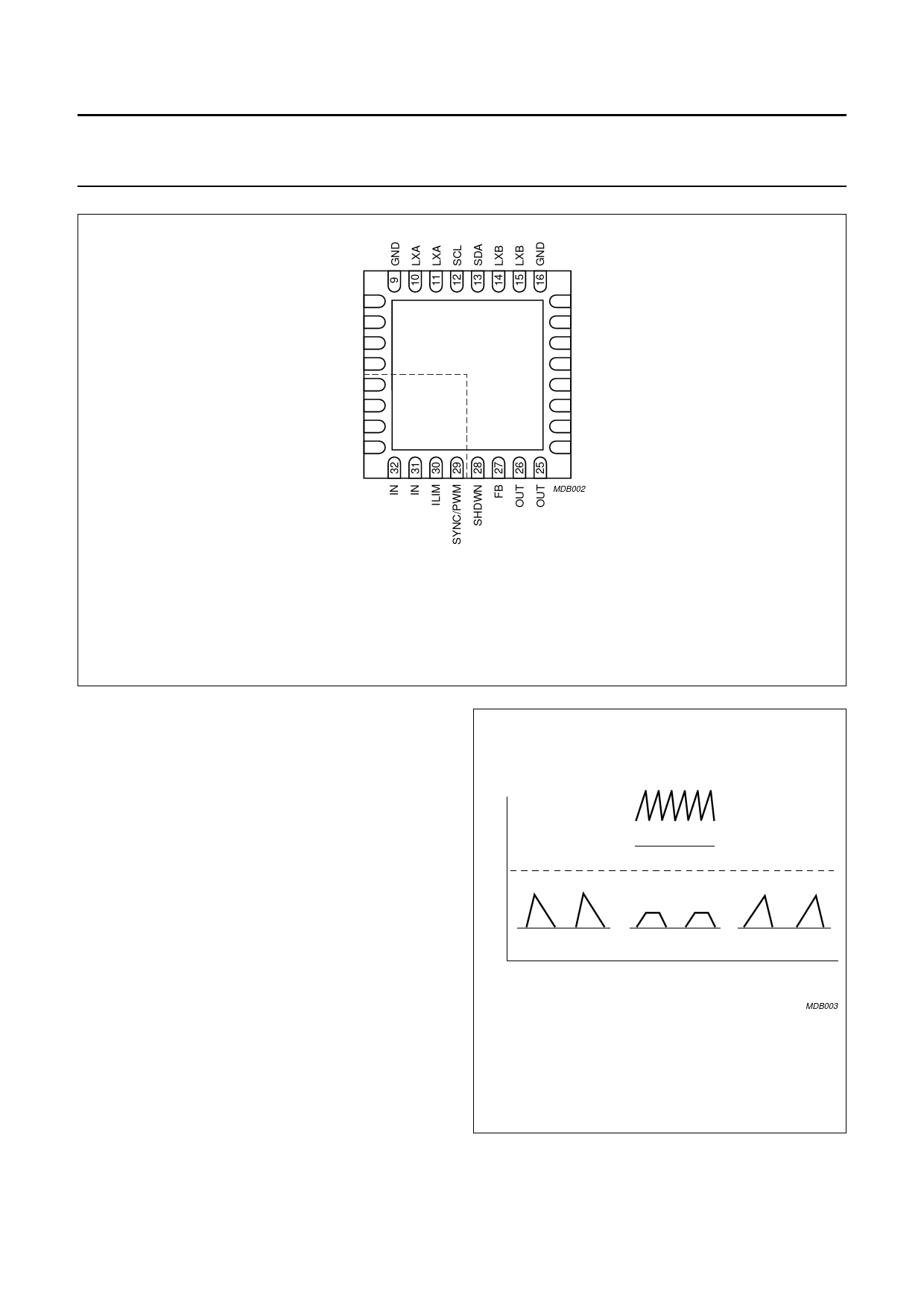
This diagram is a bottom side view.
Pin 1 is indicated with a dot on the top side of the package.
For mechanical details of HVQFN32 package, see Chapter 12.
Fig.2 Pin configuration.
7 FUNCTIONAL DESCRIPTION
7.1 Introduction
The TEA1211HN is able to operate in Pulse Frequency
Modulation (PFM) or discontinuous conduction mode as
well as in Pulse Width Modulation (PWM) or continuous
conduction mode. All switching actions are completely
determined by a digital control circuit which uses the
output voltage level as control input. This digital approach
enables the use of a new pulse width and frequency
modulation scheme, which ensures optimum power
efficiency over the complete range of operation of the
converter.
7.2 Control mechanism
Depending on load current Iload and VIN to VOUT ratio, the
controller chooses a mode of operation. When high output
power is requested, the device will operate in PWM
(continuous conduction) mode, which is a 2-phase cycle in
up- as well as in down mode. For small load currents the
controller will switch over to PFM (discontinuous mode),
which is either a 3- or 4-phase cycle depending on the
input to output ratio, see Fig.3.
handbook, halfpage
Icoil
PWM
PFM
0
VIN > VOUT
down mode
VIN = VOUT
stationary mode
VIN < VOUT
up mode
MDB003
Fig.3 Waveform of coil current as function of Iload
and VIN to VOUT ratio.
2003 Oct 13
5
Share Link: 