M80C186 Ver la hoja de datos (PDF) - Intel
Número de pieza
componentes Descripción
Fabricante
M80C186 Datasheet PDF : 59 Pages
| |||
M80C186
In-Service Register
This register can be read from or written into It con-
tains the in-service bit for each of the internal inter-
rupt sources The format for this register is shown in
Figure 36 Bit positions 2 and 3 correspond to the
DMA channels positions 0 4 and 5 correspond to
the integral timers The source’s IS bit is set when
the processor acknowledges its interrupt request
Interrupt Request Register
This register indicates which internal peripherals
have interrupt requests pending The format of this
register is shown in Figure 36 The interrupt request
bits are set when a request arrives from an internal
source and are reset when the processor acknowl-
edges the request As in master mode D0 and D1
are read write all other bits are read only
Mask Register
The register contains a mask bit for each interrupt
source The format for this register is shown in Fig-
ure 36 If the bit in this register corresponding to a
particular interrupt source is set any interrupts from
that source will be masked These mask bits are ex-
actly the same bits which are used in the individual
control registers i e changing the state of a mask
bit in this register will also change the state of the
mask bit in the individual interrupt control register
corresponding to the bit
Control Registers
These registers are the control words for all the in-
ternal interrupt sources The format of these regis-
ters is shown in Figure 37 Each of the timers and
both of the DMA channels have their own Control
Register
The bits of the Control Registers are encoded as
follows
prx 3-bit encoded field indicating a priority level
for the source note that each source must be
programmed at specified levels
msk mask bit for the priority level indicated by prx
bits
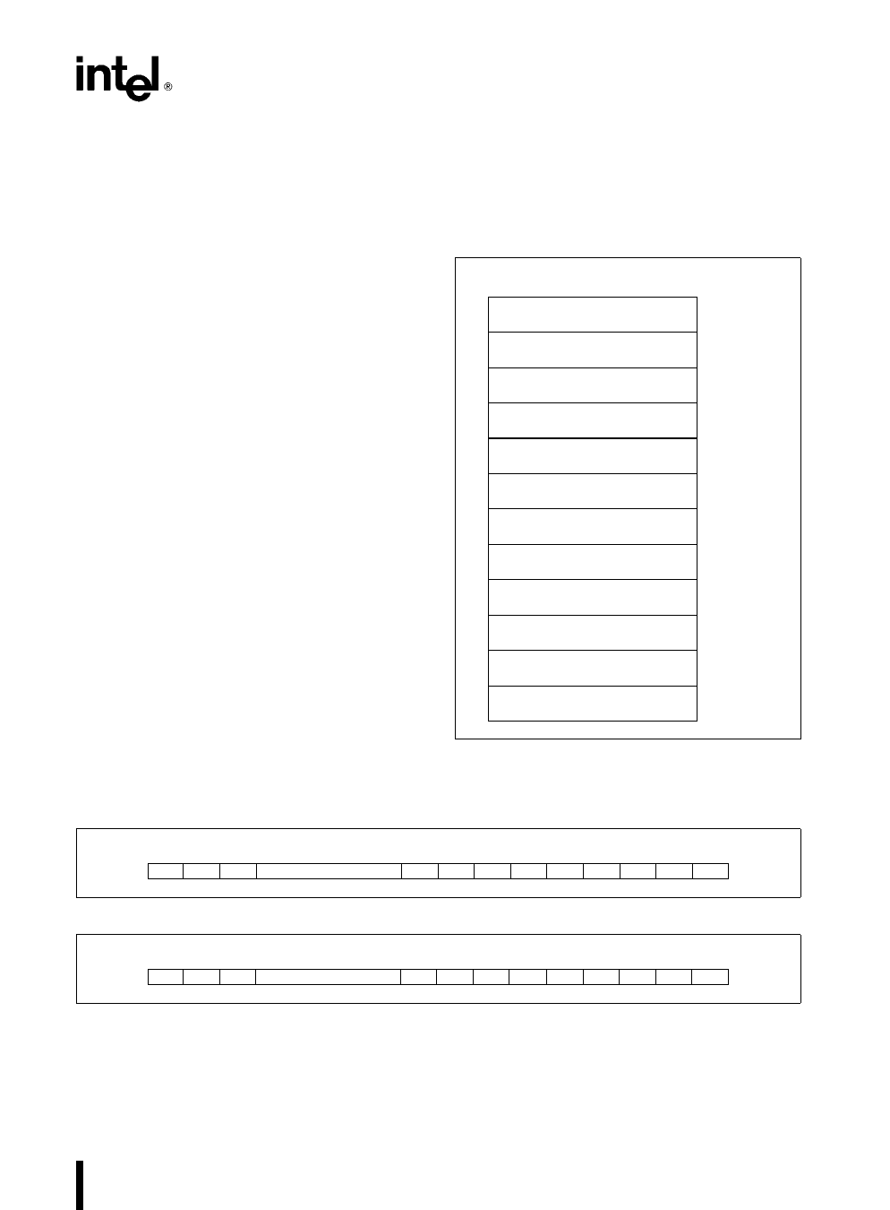
LEVEL 5 CONTROL REGISTER
(TIMER 2)
LEVEL 4 CONTROL REGISTER
(TIMER 1)
LEVEL 3 CONTROL REGISTER
(DMA 1)
LEVEL 2 CONTROL REGISTER
(DMA 0)
LEVEL 0 CONTROL REGISTER
(TIMER 0)
INTERRUPT STATUS REGISTER
OFFSET
3AH
38H
36H
34H
32H
30H
INTERRUPT-REQUEST REGISTER
2EH
IN-SERVICE REGISTER
2CH
PRIORITY-LEVEL MASK REGISTER 2AH
MASK REGISTER
28H
SPECIFIC EOI REGISTER
22H
INTERRUPT VECTOR REGISTER
20H
Figure 34 Interrupt Controller Registers
(Slave Mode)
15 14 13
8
7
6
5
4
3
2
1
0
0
0
0
0
0
0
0
0
0 L2 L1 L0
Figure 35 Specific EOI Register Format
15 14 13
8
7
6
5
4
3
2
1
0
0
0
0
0
0
0 TMR2 TMR1 D1 D0 0 TMR0
Figure 36 In-Service Interrupt Request and Mask Register Format
39
Share Link: 