M80C186 Ver la hoja de datos (PDF) - Intel
Número de pieza
componentes Descripción
Fabricante
M80C186 Datasheet PDF : 59 Pages
| |||
M80C186
sponding to a particular source serves to mask the
source from generating interrupts These mask bits
are the exact same bits which are used in the indi-
vidual control registers programming a mask bit us-
ing the mask register will also change this bit in the
individual control registers and vice versa
INT3 CONTROL REGISTER
INT2 CONTROL REGISTER
INT1 CONTROL REGISTER
INT0 CONTROL REGISTER
DMA 1 CONTROL REGISTER
DMA 0 CONTROL REGISTER
TIMER CONTROL REGISTER
INTERRUPT STATUS REGISTER
INTERRUPT REQUEST REGISTER
IN-SERVICE REGISTER
PRIORITY MASK REGISTER
MASK REGISTER
POLL STATUS REGISTER
POLL REGISTER
EOI REGISTER
OFFSET
3EH
3CH
3AH
38H
36H
34H
32H
30H
2EH
2CH
2AH
28H
26H
24H
22H
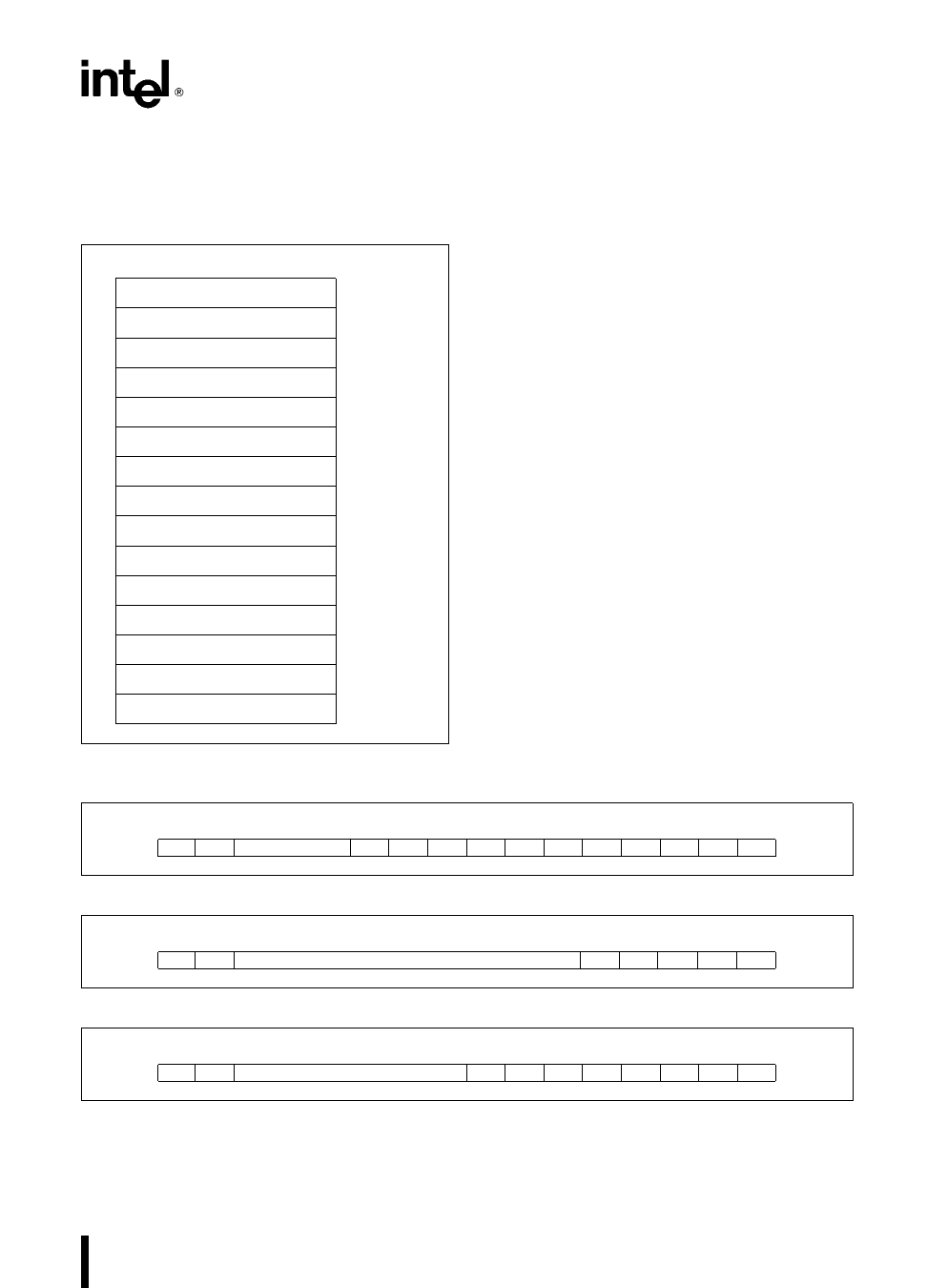
Figure 24 Interrupt Controller Registers
(Master Mode)
Priority Mask Register
This register is used to mask all interrupts below par-
ticular interrupt priority levels The format of this reg-
ister is shown in Figure 26 The code in the lower
three bits of this register inhibits interrupts of priority
lower (a higher priority number) than the code speci-
fied For example 100 written into this register
masks interrupts of level five (101) six (110) and
seven (111) The register is reset to seven (111)
upon RESET so no interrupts are masked due to
priority number
Interrupt Status Register
This register contains general interrupt controller
status information The format of this register is
shown in Figure 27 The bits in the status register
have the following functions
DHLT DMA Halt Transfer setting this bit halts all
DMA transfers It is automatically set when-
ever a non-maskable interrupt occurs and it
is reset when an IRET instruction is execut-
ed The purpose of this bit is to allow prompt
service of all non-maskable interrupts This
bit may also be set by the programmer
IRTx
These three bits represent the individual tim-
er interrupt request bits These bits are used
to differentiate the timer interrupts since the
timer IR bit in the interrupt request register is
the ‘‘OR’’ function of all timer interrupt re-
quest Note that setting any one of these
three bits initiates an interrupt request to the
interrupt controller
15 14
10 9
8
7
6
5
4
3
2
1
0
0
0
0
0
0 13 12 I1 I0 D1 D0 0 TMR
Figure 25 In-Service Interrupt Request and Mask Register Formats
15 14
0
0
3
2
1
0
0 PRM2 PRM1 PRM0
Figure 26 Priority Mask Register Format
15 14
DHLT 0
7
6
5
4
3
2
1
0
0
0
0
0
0 IRT2 IRT1 IRT0
Figure 27 Interrupt Status Register Format (Master Mode)
35
Share Link: 