HT49R50 Ver la hoja de datos (PDF) - Holtek Semiconductor
Número de pieza
componentes Descripción
Fabricante
HT49R50 Datasheet PDF : 59 Pages
| |||
HT49R50
Functional Description
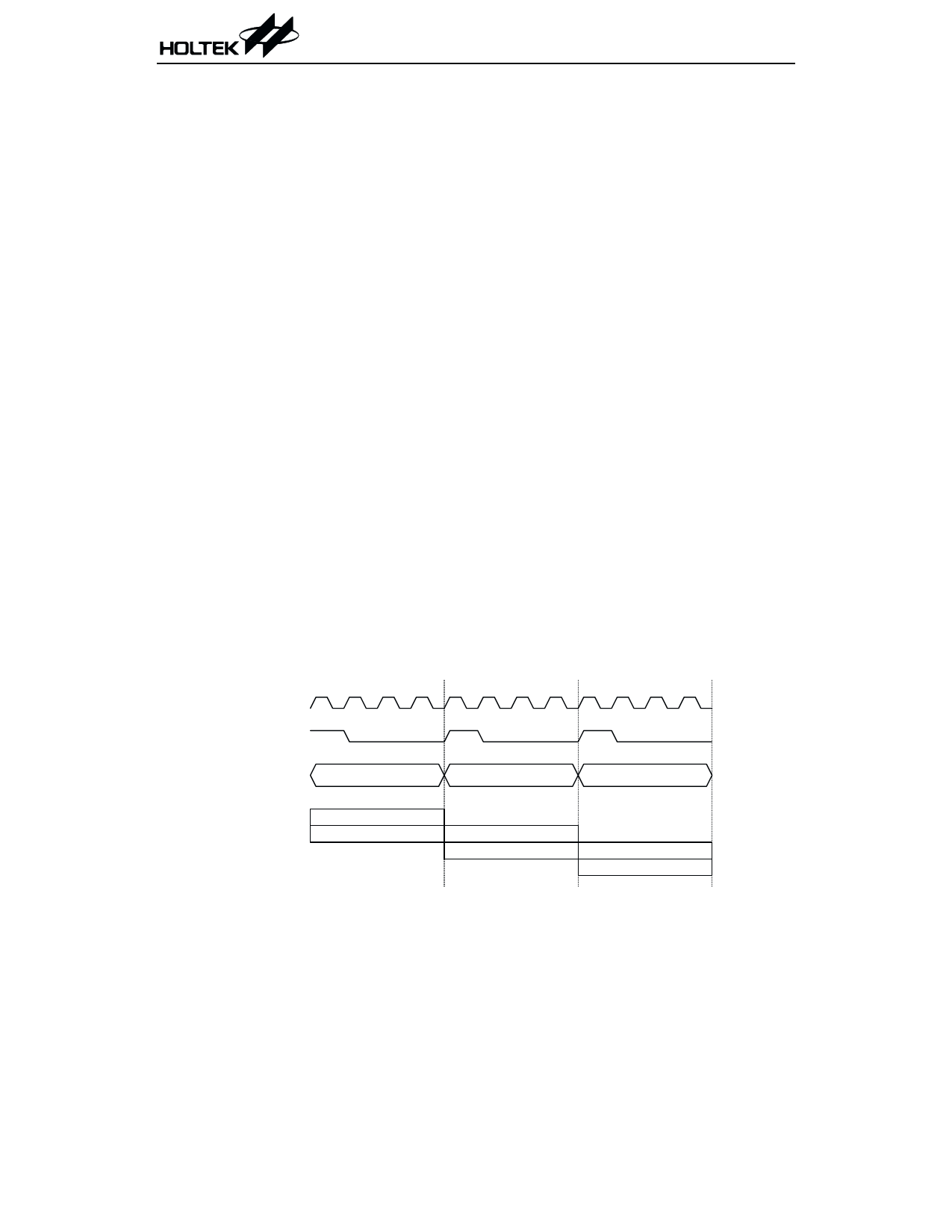
Execution flow
The system clock is derived from either a crys-
tal or an RC oscillator. It is internally divided
into four non-overlapping clocks. One instruc-
tion cycle consists of four system clock cycles.
Instruction fetching and execution are
pipelined in such a way that a fetch takes one
instruction cycle while decoding and execution
takes the next instruction cycle. The pipelining
scheme causes each instruction to effectively
execute in a cycle. If an instruction changes the
value of the program counter, two cycles are re-
quired to complete the instruction.
Program counter - PC
The program counter (PC) is of 12 bits wide and
controls the sequence in which the instructions
stored in the program ROM are executed. The
contents of the PC can specify a maximum of
4096 addresses.
After accessing a program memory word to
fetch an instruction code, the value of the PC is
incremented by one. The PC then points to the
memory word containing the next instruction
code.
When executing a jump instruction, conditional
skip execution, loading a PCL register, a sub-
routine call, an initial reset, an internal inter-
rupt, an external interrupt, or returning from a
subroutine, the PC manipulates the program
transfer by loading the address corresponding
to each instruction.
The conditional skip is activated by instruc-
tions. Once the condition is met, the next in-
struction, fetched during the current
instruction execution, is discarded and a
dummy cycle replaces it to get a proper instruc-
tion; otherwise proceed with the next instruc-
tion.
The lower byte of the PC (PCL) is a readable
and writeable register (06H). Moving data into
the PCL performs a short jump. The destina-
tion is within 256 locations.
When a control transfer takes place, an addi-
tional dummy cycle is required.
Program memory - EPROM
The program memory (EPROM) is used to store
the program instructions which are to be exe-
cuted. It also contains data, table, and inter-
rupt entries, and is organized into 4096 ´ 15
bits which are addressed by the PC and table
pointer.
Certain locations in the ROM are reserved for
special usage:
· Location 000H
Location 000H is reserved for program initial-
ization. After chip reset, the program always
begins execution at this location.
T1 T2 T3 T4 T1 T2 T3 T4 T1 T2 T3 T4
S y s te m C lo c k
O S C 2 ( R C o n ly )
PC
PC
PC +1
PC +2
F e tc h IN S T (P C )
E x e c u te IN S T (P C -1 )
F e tc h IN S T (P C + 1 )
E x e c u te IN S T (P C )
Execution flow
F e tc h IN S T (P C + 2 )
E x e c u te IN S T (P C + 1 )
9
October 22, 1999
Share Link: 