NJU8721 Ver la hoja de datos (PDF) - Japan Radio Corporation
Número de pieza
componentes Descripción
Fabricante
NJU8721 Datasheet PDF : 13 Pages
| |||
NJU8721
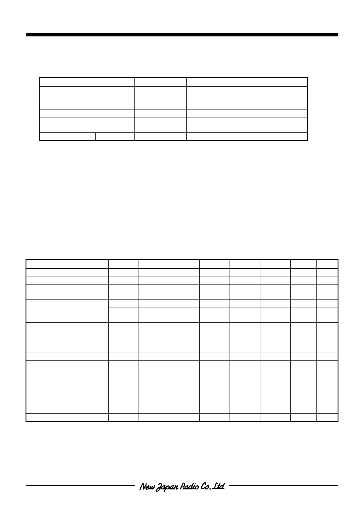
! ABSOLUTE MAXIMUM RATINGS
PARAMETER
Supply Voltage
Input Voltage
Operating Temperature
Storage Temperature
Power Dissipation SSOP20
SYMBOL
VDD
VDDL
VDDR
Vin
Topr
Tstg
PD
RATING
-0.3 to +4.0
-0.5 to +5.5
-0.5 to +5.5
-0.3 to VDD+0.3
-40 to +85
-40 to +125
300
(Ta=25°C)
UNIT
V
V
V
V
°C
°C
mW
Note 1) All voltage values are specified as VSS= VSSR= VSSL=0V.
Note 2) If the LSI is used on condition beyond the absolute maximum rating, the LSI may be destroyed. Using
LSI within electrical characteristics is strongly recommended for normal operation. Use beyond the
electrical characteristics conditions will cause malfunction and poor reliability.
Note 3) Decoupling capacitors should be connected between VDD-VSS, VDDR-VSSR and VDDL-VSSL due to the
stabilized operation.
! ELECTRICAL CHARACTERISTICS
PARAMETER
VDDL, VDDR Supply Voltage
VDD Supply Voltage
Output Power Efficiency
Output THD
Output Power
S/N
Dynamic Range
Channel Separation
Output Level Difference
Between Lch and Rch
Maximum Mute Attenuation
Passband Response
Power Supply Current
At Standby
Power Supply Current
At Operating
Input Voltage
Input Leakage Current
(Ta=25°C, VDD=VDDL=VDDR=3.3V, fS=44.1kHz, Input Signal=1kHz,
Input Signal Level at Full Scale Output, MCK=256fS, Load Impedance=16Ω,
Measuring Band=20Hz to 20kHz, 2nd-order 34kHz LC Filter (Q=0.75),
unless otherwise noted)
SYMBOL CONDITIONS
MIN.
TYP.
MAX. UNIT Note
VDD
-
5.25
V
3.0
3.3
3.6
V
Eeff Vo= 0dB
80
-
-
%
4
THD16 Po=3mW,RL=16Ω
-
-
0.1
%
Po16 Vo= 0dB,RL=16Ω
22
48
-
mW/ch
Po08 Vo= 0dB,RL=8Ω
40
80
-
mW/ch
SN
A weight
85
90
-
dB
Drange A weight
85
90
-
dB
Echn EIAJ(1kHz)
60
-
-
dB
CHD
-
-
3
dB
MAT
90
-
-
dB
PR
20Hz to 20kHz
-
-
±1
dB
5
IST
Stopping MCK,
BCK, LRCK, DIN
-
-
10
µA
IDD
No-load operating
No signal inputted
-
9
14
mA
VIH
0.7VDD
-
VDD
V
VIL
0
-
0.3VDD
V
ILK
-
-
±1.0
µA
Note 4)
Power Efficiency (%) =
OUTL Output Power + OUTR Output Power (W)
VDDL Supply Power + VDDR Supply Power (W)
× 100
Note 5) When the cut-off frequency is 10Hz or less using external AC-coupling capacitor.
-9-
Share Link: 