LT3465A Ver la hoja de datos (PDF) - Linear Technology
Número de pieza
componentes Descripción
Fabricante
LT3465A Datasheet PDF : 12 Pages
| |||
LT3465A
APPLICATIO S I FOR ATIO
Open Circuit Protection
The LT3465A has an internal open-circuit protection cir-
cuit. When the LEDs are disconnected from the circuit or
fail open, VOUT is clamped at 30V. The LT3465A will then
switch at a low frequency, minimizing input current. VOUT
and input current during open circuit are shown in the
Typical Performance Characteristics.
Board Layout Consideration
As with all switching regulators, careful attention must be
paid to the PCB board layout and component placement.
To maximize efficiency, switch rise and fall times are made
as short as possible. To prevent electromagnetic interfer-
ence (EMI) problems, proper layout of the high frequency
switching path is essential. Place COUT next to the VOUT
pin. Always use a ground plane under the switching
regulator to minimize interplane coupling. In addition, the
ground connection for the feedback resistor R1 should be
tied directly to the GND pin and not shared with any other
component, ensuring a clean, noise-free connection. Rec-
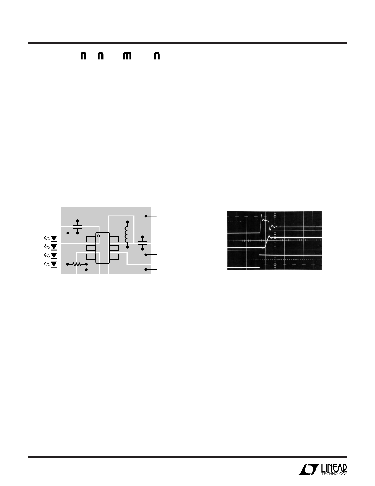
ommended component placement is shown in Figure 7.
Start-Up Input Current
As previously mentioned, the LT3465A does not have an
internal soft-start circuit. Inrush current can therefore rise
to approximately 400mA as shown in Figure 8 when
driving 4 LEDs. The LT3465 has an internal soft-start
circuit and is recommended if inrush current must be
minimized.
COUT
1
2
RFB
3
GND
L
6
5
4
CIN
VIN
3465 F07
CTRL
Figure 7. Recommended Component Placement
IIN
200mV/DIV
FB
200mV/DIV
CTRL
2V/DIV
50µs/DIV
Figure 8.
3465A F06b
3465ai
8
Share Link: 