LT3465A Ver la hoja de datos (PDF) - Linear Technology
Número de pieza
componentes Descripción
Fabricante
LT3465A Datasheet PDF : 12 Pages
| |||
LT3465A
APPLICATIO S I FOR ATIO
Table 3 gives inrush peak currents for some component
selections.
Table 3. Inrush Peak Current
VIN (V)
5
r (Ω)
0.5
5
0.5
3.6
0.5
5
0.5
L (µH)
22
22
22
33
C (µF)
0.22
1
0.22
1
IP (A)
0.38
0.70
0.26
0.60
LED Current and Dimming Control
The LED current is controlled by the feedback resistor (R1
in Figure 1) and the feedback reference voltage.
ILED = VFB/RFB
The CTRL pin sets the feedback reference voltage as
shown in the Typical Performance Characteristics. When
CTRL is at 1.8V or more, the feedback reference is 200mV,
which results in full-scale LED current. The CTRL pin can
be used as a dimming control when its voltage is between
200mV to 1.5V. To maintain LED current accuracy, a 1%
or better resistor for R1 is recommended. The formula and
table for RFB selection are shown below:
RFB = 200mV/ILEDF
where ILEDF is full-scale LED current
Table 4. RFB Resistor Value Selection
ILED (mA)
5
10
15
20
R1 (Ω)
40.2
20.0
13.3
10.0
Dimming Using Filtered PWM
Dimming can be realized by using an RC filter in front of the
CTRL pin to filter a PWM signal, as depicted in Figure 5.
The filtered PWM signal is equivalent to a constant volt-
age. The time constant R1 • C1 should be much lower than
the frequency of the PWM signal. Additionally, R1 should
be small compared to the 50kΩ impedance of the CTRL
pin. Suggested values are shown in Figure 5.
R1
5k
PWM
LT3465
CTRL
C1
100nF
3465 F06
Figure 5. Dimming Control Using a Filtered PWM Signal
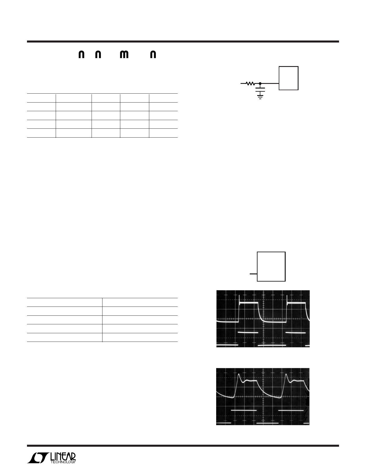
Dimming Using Direct PWM
Unlike the LT3465, the LT3465A does not have internal
soft-start. Although the input current is higher during
start-up, the absence of soft-start allows the CTRL pin to
be directly driven with a PWM signal for dimming. A zero
percent duty cycle sets the LED current to zero, while
100% duty cycle sets it to full current. Average LED current
increases proportionally with the duty cycle of the PWM
signal. PWM frequency should be between 1kHz and
10kHz for best performance. The PWM signal should be at
least 1.8V in magnitude; lower voltage will lower the
feedback voltage as shown in Equation 1. Waveforms are
shown for a 1kHz PWM and 10kHz PWM signal in Figures
6a and 6b respectively.
PWM
LT3465A
CTRL
FB
100mV/DIV
CTRL
2V/DIV
FB
100mV/DIV
CTRL
2V/DIV
200µs/DIV (1kHz)
Figure 6a.
3465A F06a
20µs/DIV (10kHz)
Figure 6b.
3465A F06b
3465ai
7
Share Link: 