EL2021 Ver la hoja de datos (PDF) - Intersil
Número de pieza
componentes Descripción
Fabricante
EL2021 Datasheet PDF : 8 Pages
| |||
EL2021
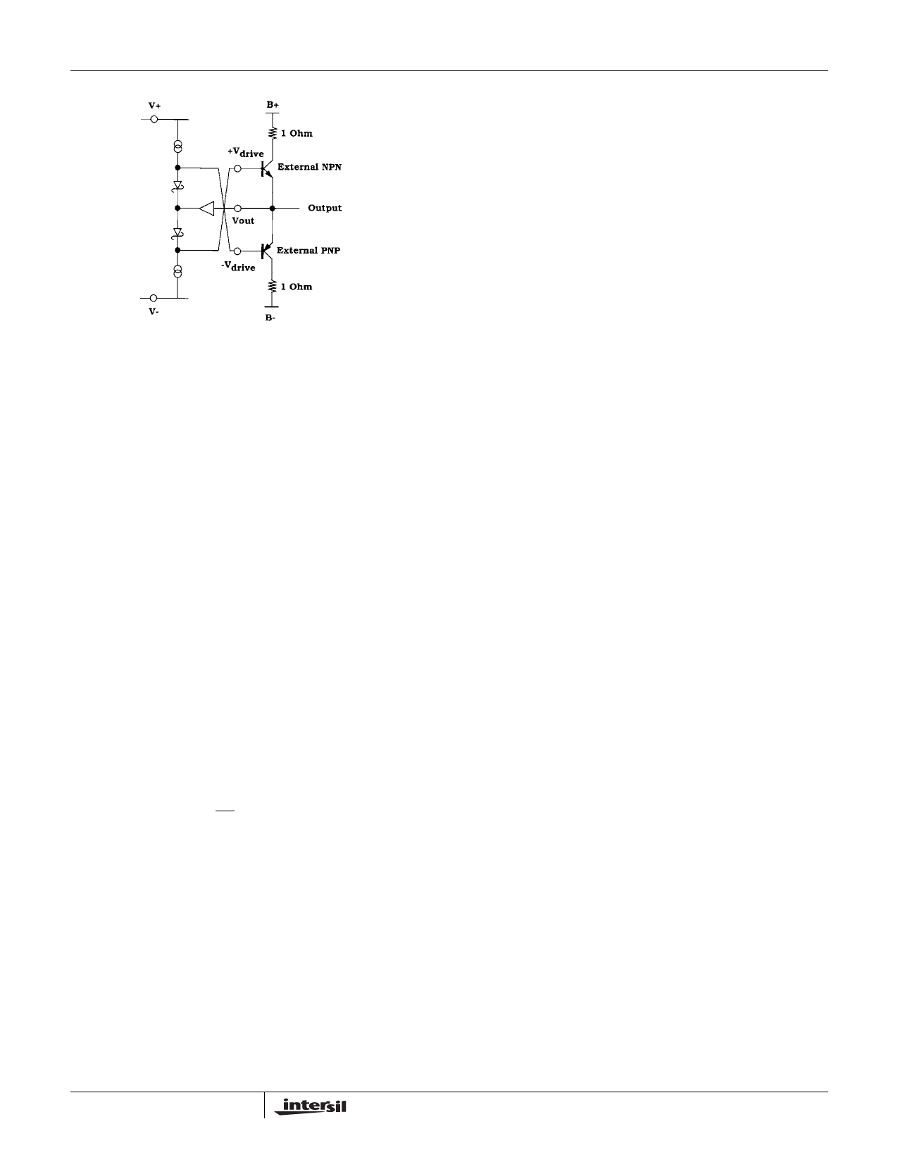
FIGURE 2. SIMPLIFIED OUTPUT STAGE (HIGH-IMPEDANCE
MODE)
Power Supplies
In typical operation, V+ and V- can be as much as ±15V and
as little as VCH +3V and VCL -3V, respectively. When driving
heavy output currents, however, it is wise to have 5V of
headroom above VCH and below VCL to ensure no
saturation of devices within the EL2021 and attendant
waveshape distortions. Thus, for VCH = 5V and VCL = -2V,
minimum operating voltages are +10, -7V. It is very important
to bypass the supply terminals with low-inductance
capacitors to ground, since the full base drive currents of the
output transistors are derived from these supplies. Because
the pulse currents can reach 60mA, the capacitors should be
at least a microfarad; 4.7µF tantalum are ideal and require
no small bypasses in parallel.
B+ and B- can be any voltage within V+ and V- and some
amount previously discussed above VCH and below VCL. If
VCH or VCL exceeds B+ or B-, very large internal fault
currents can flow when the EL2021 attempts to bring an
output transistor's base beyond the collector voltage. The
bypassing care of the V± lines apply to the B± lines, as well
as the fact that ampere currents can occur. Large (100µF–
500µF) capacitors should be used to bypass perhaps every
tenth EL2021.
The VCH, VCL, Data and OE lines should be driven locally so
as to not pick up magnetic interference from the output. The
inductance of interconnects to these lines can allow coupling
to cause waveshape anomalies or even oscillations. If long
lines are unavoidable, local 1k resistors or 50pF–100pF
capacitors to ground can also serve the purpose.
Data Pin
The slew rate of the input to the Data pin should be kept less
than 1000V/µs. Some feedthrough can occur for large Slew
Rates which will distort the output waveshape. A 1k–2k
resistor in series with the data pin will reduce feedthrough.
Current Sense
The output current is sensed by comparing the voltage
dropped across the external shunt resistors to an internal
0.45V reference. The center of the trip level is adjusted for
the particular output transistor betas listed in the data
specifications. Transistors with less beta at high currents will
cause the sense comparators to trip at slightly higher output
currents. The 1Ω shunt resistors should be non-inductive.
The family of wirewound resistors called “non-inductive” are
too inductive for these shunts.
The response of the Sense Out can be thought of as slow
attack and fast decay. A continuous overcurrent condition
must last for at least 2µs before Sense Out will go high, but
will clear to low only about 200ns after the overcurrent is
withdrawn. This allows transient currents due to slewing
capacitive load to not generate a flag. On the other hand, the
output transistors will not be damaged with only a 2µs
system reaction time to a short-circuit.
Construction Practices
The major cautions in connecting to the EL2021 involve
magnetic rather than capacitive parasitic concerns. The
circuits can output as much as 100A/µs. Even with normal
Slew Rates and moderately large capacitive loads, the dI/dT
can cause magnetic fields in harmless looking wires to fill
adjacent lines with noise, and sometimes ringing or even
sustained feedback. Thus, rules for wiring the EL2021 are:
1. Keep leads short and large. Short wires are less
inductive, as are wires with large surface area. The large
surface area also reduces skin resistance at high
frequencies, important at high currents (at 100MHz,
current penetrates only a few microns in metals).
2. Use a ground plane. Due to inductance and skin effect,
“ground” voltages will be different only inches apart on a
copper ground plane. Individual wires do not create
ground at high frequencies. The common “star” ground is
a very bad idea for high-current and high-frequency
circuits.
3. Dress all wires against the ground plane. The magnetic
fields that the wires would have generated will be
intercepted by the ground plane and absorbed, thus
reducing the wire's effective inductance. The capacitance
added by this method is not important to EL2021
operation.
4. The external transistors should have short interconnects
to the EL2021, the collector shunt resistors, and the
bypass capacitors. As previously stated, the shunt
resistors must not be wire wound because of their
inductance.
5. The bypass capacitors should have low series resistance
and inductance, but should not have a high Q. This may
seem contradictory, but a 4.7µF tantalum capacitor
seems to work the best. An electrolytic capacitor should
be added to help bolster the supply levels in the 0.1µs–
1µs after a transition. No small capacitors are needed in
parallel with the tantalums. The bypasses' ground returns
7
Share Link: 