DS2404 Ver la hoja de datos (PDF) - Dallas Semiconductor -> Maxim Integrated
Número de pieza
componentes Descripción
Fabricante
DS2404 Datasheet PDF : 28 Pages
| |||
DS2404
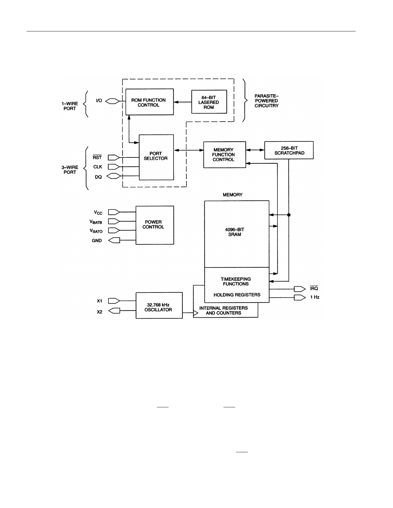
The “Power Control” section provides for two basic power configurations, battery operate mode and VCC
operate mode. The battery operate mode utilizes one supply connected to VBATO . The VCC operate mode
may utilize two supplies; the primary supply connects to VCC and a backup supply connects to VBATB .
DS2404 BLOCK DIAGRAM Figure 1
COMMUNICATION PORTS
Two communication ports are provided, a 1-Wire and a 3-wire port. The advantages of using the 1-Wire
port are as follows: 1) provides access to the 64-bit lasered ROM, 2) consists of a single communication
signal (I/O), and 3) multiple devices may be connected to the 1-Wire bus. The 1-Wire bus has a
maximum data rate of 16.3k bits/second and requires one 5kΩ external pullup.
The 3-wire port consists of three signals, RST , CLK, and DQ. RST is an enable input, DQ is bidirectional
serial data, and the CLK input is used to clock in or out the serial data. The advantages of using the 3-
wire port are 1) high data transfer rate (2 MHz), 2) simple timing, and 3) no external pullup required.
Port selection is accomplished on a first-come, first-serve basis. Whichever port comes out of reset first
will obtain control. For the 3-wire port, this is done by bringing RST high. For the 1-Wire port, this is
done on the first falling edge of I/O after the reset and presence pulses. (See “1-Wire Signaling” section.)
3 of 28
020998
Share Link: 