DS2282 Ver la hoja de datos (PDF) - Dallas Semiconductor -> Maxim Integrated
Número de pieza
componentes Descripción
Fabricante
DS2282 Datasheet PDF : 22 Pages
| |||
DS2282
OVERVIEW
The DS2282 completely controls the Facility Data Link
(FDL) in T1 environments. It can handle the FDL re-
quirements outlined in American National Standards
Institute (ANSI) document T1.403–1989 or those out-
lined in the AT&T publication TR 54016 (1986/89). Re-
covered data from a T1 line is clocked into the DS2282
via the RPOS and RNEG pins with the RCLK signal.
See Figure 1. The DS2282 synchronizes to the incom-
ing data stream and extracts the FDL. Then, it will de-
code the incoming messages on the FDL and properly
create the FDL messages that must be transmitted.
An asynchronous serial port is used to control the
DS2282 and to retrieve data from it. The port is oper-
ated at 19.2 Kbps. Access to the onboard registers is
achieved through the serial port via the TXD and RXD
pins. An address can be assigned to this serial port.
This allows a single external controller to communicate
over a single bus to as many as 31 separate DS2282’s.
See Figure 2. Each DS2282 will listen for its address
and only respond when it is asked to do so.
Most of the clearable registers in the DS2282 that either
count error events or errored time intervals are recorded
in onboard, nonvolatile memory. Hence, in case of a lo-
cal loss of power, these registers will maintain their
counts.
Two typical applications of the DS2282 are shown in
Figures 3A and 3B. In these applications, the DS2282 is
completely controlling the FDL as well as monitoring the
T1 line. The DS2250 Micro Stik is used to configure the
DS2282 and to extract any performance data that may
be required. In these applications, the DS2250 is also
used to control either the DS2283 Enhanced T1 Line
Card Stik or the DS2180A T1 Transceiver. The DS2282
can also be operated without an external controller. See
Hardware Mode section and Table 7.
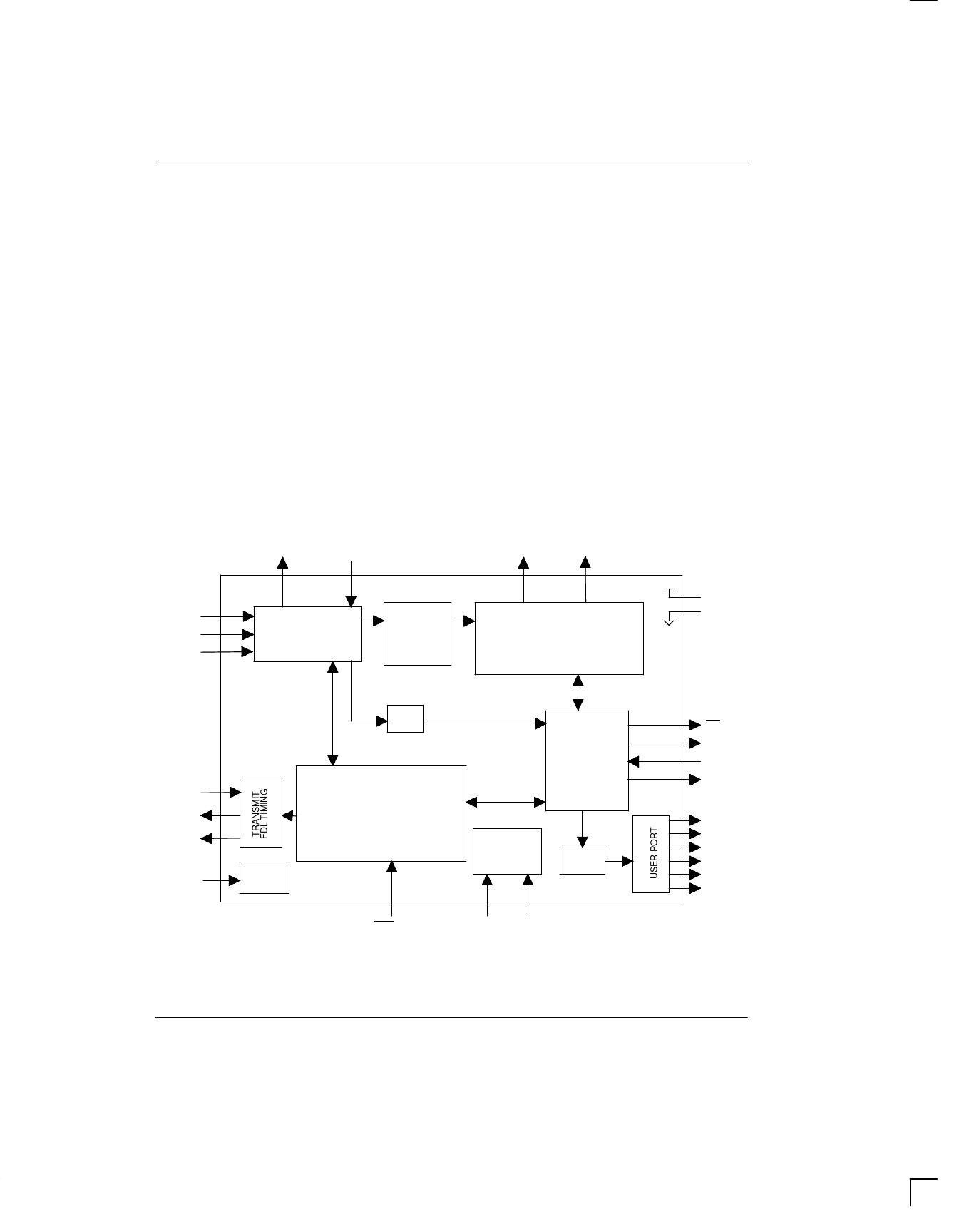
DS2282 BLOCK DIAGRAM Figure 1
RLOS(2)
B8ZS(20)
LLB(26)
PLB(14)
RCLK(3)
RPOS(4)
RNEG(5)
SYNCHRONIZER
ERROR
DETECTOR
FDL
EXTRACTOR
PERFORMANCE REPORT MESSAGE
UNSCHEDULED MESSAGE
MAINTENANCE MESSAGE DECODER
VDD(1)
GND(23)
TLCLK(12)
TLINK(28)
PRMXA(8)
RST(21)
SR
SERIAL PORT
CONTROLLER
RESET
PERFORMANCE REPORT MESSAGE
UNSCHEDULED MESSAGE
MAINTENANCE MESSAGE DECODER
NONVOLATILE
MEMORY
UBR
SLIP(13)
PSEN(27) PAS(15)
INT(7)
TXD(11)
RXD(10)
DRVEN(9)
UB1(16)
UB2(17)
UB3(18)
UB4(19)
UB5(24)
UB6(25)
022798 2/22
Share Link: 