BUJ303A(2011) Ver la hoja de datos (PDF) - NXP Semiconductors.
Número de pieza
componentes Descripción
Fabricante
BUJ303A Datasheet PDF : 14 Pages
| |||
NXP Semiconductors
BUJ303A
NPN power transistor
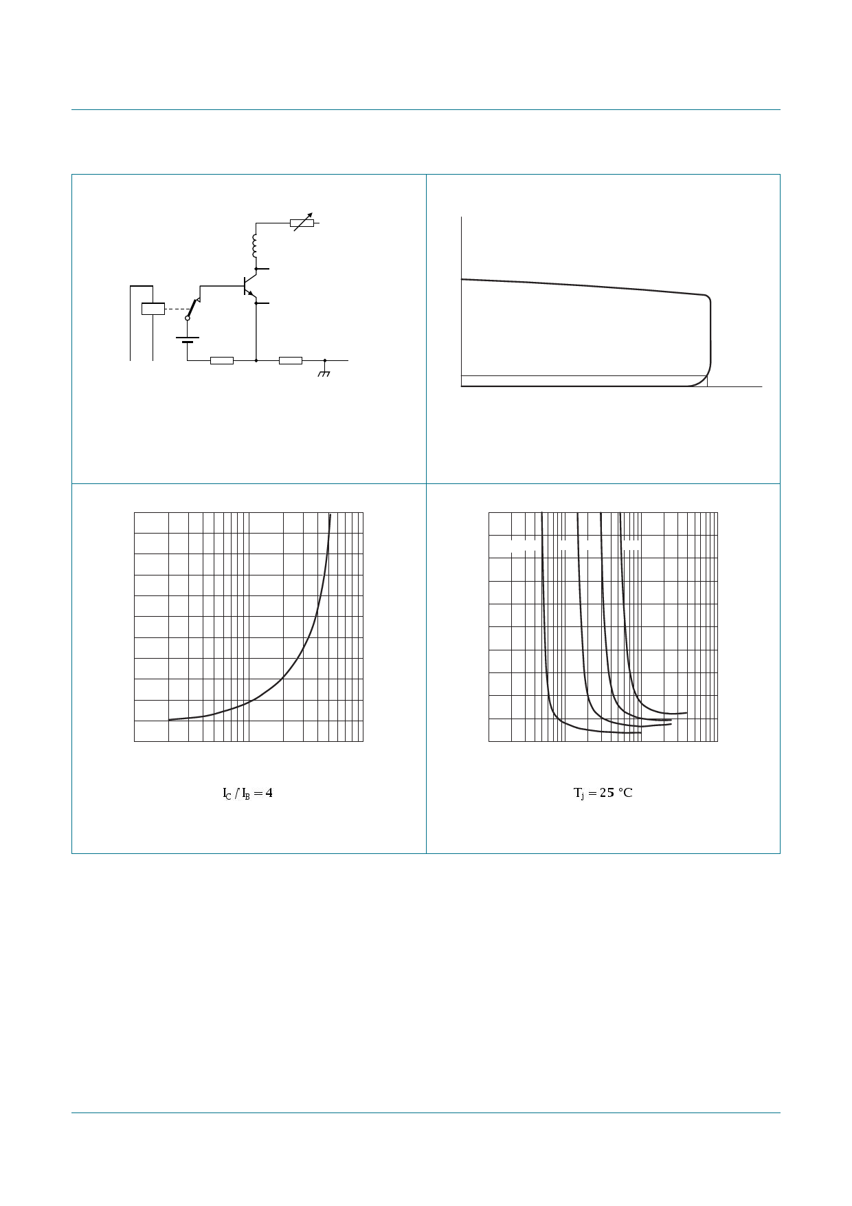
6. Characteristics
Table 6. Characteristics
Symbol
Parameter
Conditions
Min
Static characteristics
ICES
ICBO
ICEO
collector-emitter cut-off
current
VBE = 0 V; VCE = 1000 V; Tmb = 25 °C [1] -
VBE = 0 V; VCE = 1000 V; Tj = 125 °C [1] -
collector-base cut-off current VCB = 1000 V; IE = 0 A; Tmb = 25 °C [1] -
collector-emitter cut-off
current
VCE = 500 V; IB = 0 A; Tmb = 25 °C
[1] -
IEBO
emitter-base cut-off current VEB = 9 V; IC = 0 A; Tmb = 25 °C
-
VCEOsus
collector-emitter sustaining IB = 0 A; IC = 100 mA; LC = 25 mH;
500
voltage
Tmb = 25 °C; see Figure 6;
see Figure 7
VCEsat
collector-emitter saturation IC = 3 A; IB = 0.6 A; Tmb = 25 °C;
-
voltage
see Figure 8; see Figure 9
VBEsat
base-emitter saturation
IC = 3 A; IB = 0.6 A; Tmb = 25 °C;
-
voltage
see Figure 10
hFE
DC current gain
IC = 5 mA; VCE = 5 V; Tmb = 25 °C;
10
see Figure 11
IC = 500 mA; VCE = 5 V; Tmb = 25 °C;
14
see Figure 11
hFEsat
DC saturation current gain IC = 2.5 A; VCE = 5 V; Tmb = 25 °C;
10
see Figure 11
IC = 3 A; VCE = 5 V; Tmb = 25 °C;
-
see Figure 11
Dynamic characteristics
ton
turn-on time
ts
storage time
IC = 2.5 A; IBon = 0.5 A; IBoff = -0.5 A;
-
RL = 75 Ω; VBB = -4 V; Tmb = 25 °C;
-
resistive load; see Figure 12;
see Figure 13
IC = 2.5 A; IBon = 0.5 A; VBB = -5 V;
-
LB = 1 µH; Tmb = 25 °C; inductive
load; see Figure 14; see Figure 15
IC = 2.5 A; IBon = 0.5 A; VBB = -5 V;
-
LB = 1 µH; Tj = 100 °C; inductive load;
see Figure 14; see Figure 15
tf
fall time
IC = 2.5 A; IBon = 0.5 A; IBoff = -0.5 A;
-
RL = 75 Ω; VBB = -4 V; Tmb = 25 °C;
resistive load; see Figure 12;
see Figure 13
IC = 2.5 A; IBon = 0.5 A; VBB = -5 V;
-
LB = 1 µH; Tmb = 25 °C; inductive
load; see Figure 14; see Figure 15
IC = 2.5 A; IBon = 0.5 A; VBB = -5 V;
-
LB = 1 µH; Tj = 100 °C; inductive load;
see Figure 14; see Figure 15
[1] Measured with half-sine wave voltage (curve tracer).
Typ Max Unit
-
1
mA
-
2
mA
-
1
mA
-
0.1 mA
-
0.1 mA
-
-
V
0.25 1.5 V
0.97 1.3 V
22
35
25
35
13.5 17
12
-
0.5 0.7 µs
3.3 4
µs
1.4 1.6 µs
1.7 1.9 µs
0.33 0.45 µs
145 160 ns
160 200 ns
BUJ303A
Product data sheet
All information provided in this document is subject to legal disclaimers.
Rev. 05 — 3 May 2011
© NXP B.V. 2011. All rights reserved.
6 of 14
Share Link: 