AN8018SA Ver la hoja de datos (PDF) - Panasonic Corporation
Número de pieza
componentes Descripción
Fabricante
AN8018SA
Panasonic Corporation

AN8018SA Datasheet PDF : 26 Pages
| |||
AN8018SA
s Application Notes (continued)
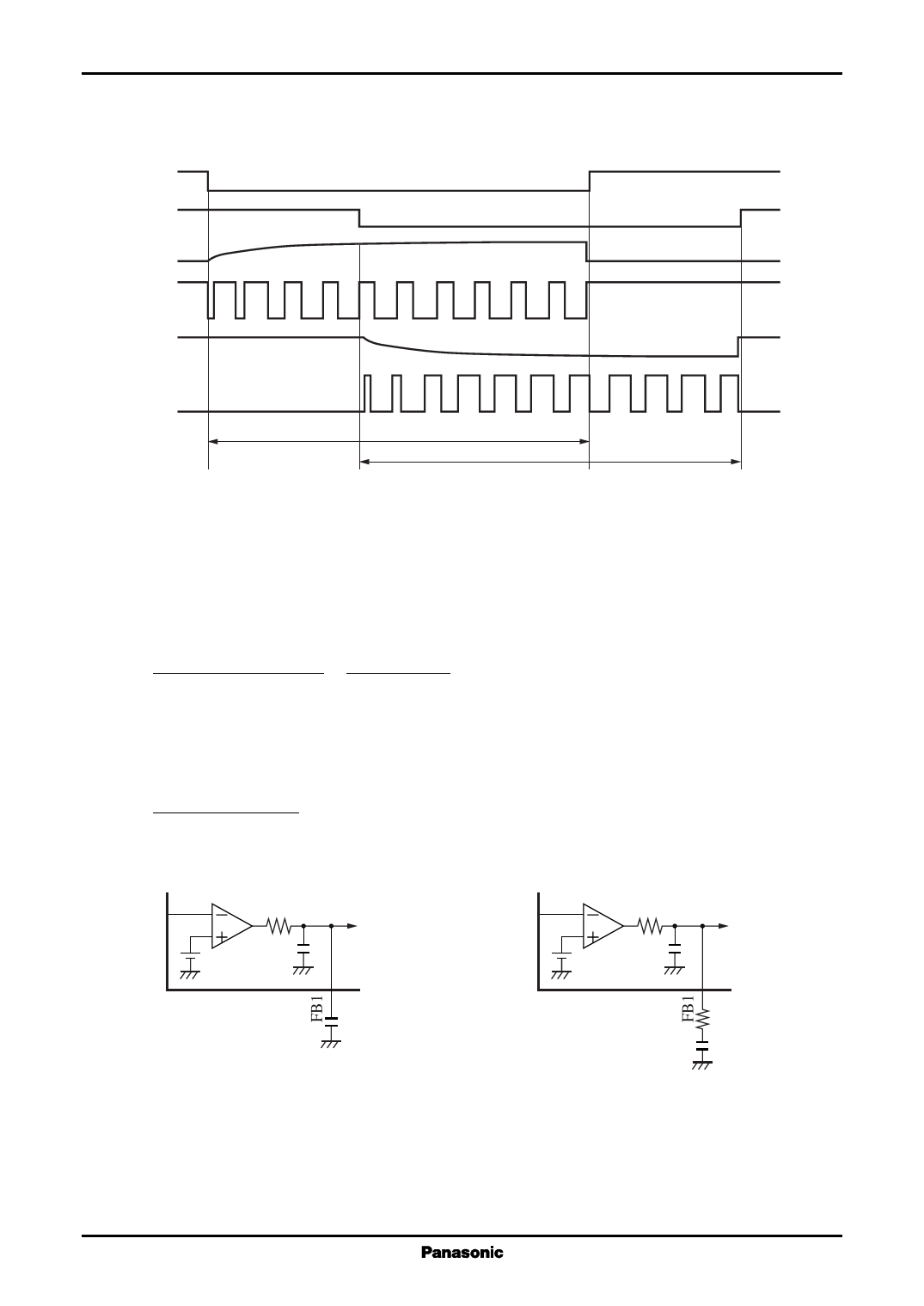
[9] About sequential operation (continued)
V1
V2
DT1
Out1
DT2
Voltage Regulators
Out2
Out1 operation
Out2 operation
Operation when each channel single on/off
[10] Error amplifier phase-compensation setting method
The equivalent circuit of error amplifier is as shown in figure 11.
The transfer function is:
H=
1 / {S (CE1 + CO1)}
RE1 + 1 / {S (CE1 + CO1)}
=
1
SCO1 · RE1 + 1
(from CE1 << CO1)
The cut-off frequency is variable by changing the externally attached phase compensation capacitor CO1 .
Adjust by inserting a resistor RO1 between the FB1 terminal and CO1 in series as shown in figure 12 when it is
required to have a gain on the high frequency side or desired to lead a phase.
The transfer function is:
H=
SCO1 · RO1 + 1
SCO1 (RO1 + RE1) + 1
(from CE1 << CO1)
IN−1
RE1
1 MΩ
57dB
CE1
1.19 V 5 pF
To PWM
CO1
Figure 11. Error amplifier equivalent circuit
IN−1
RE1
1 MΩ
57dB
CE1
1.19 V 5 pF
To PWM
RO1
CO1
Figure 12. Error amplifier equivalent circuit (RO1 inserted)
20
Share Link: