AN8018SA Ver la hoja de datos (PDF) - Panasonic Corporation
Número de pieza
componentes Descripción
Fabricante
AN8018SA
Panasonic Corporation

AN8018SA Datasheet PDF : 26 Pages
| |||
AN8018SA
Voltage Regulators
s Application Notes (continued)
[7] Parallel synchronous operation of multiple ICs (continued)
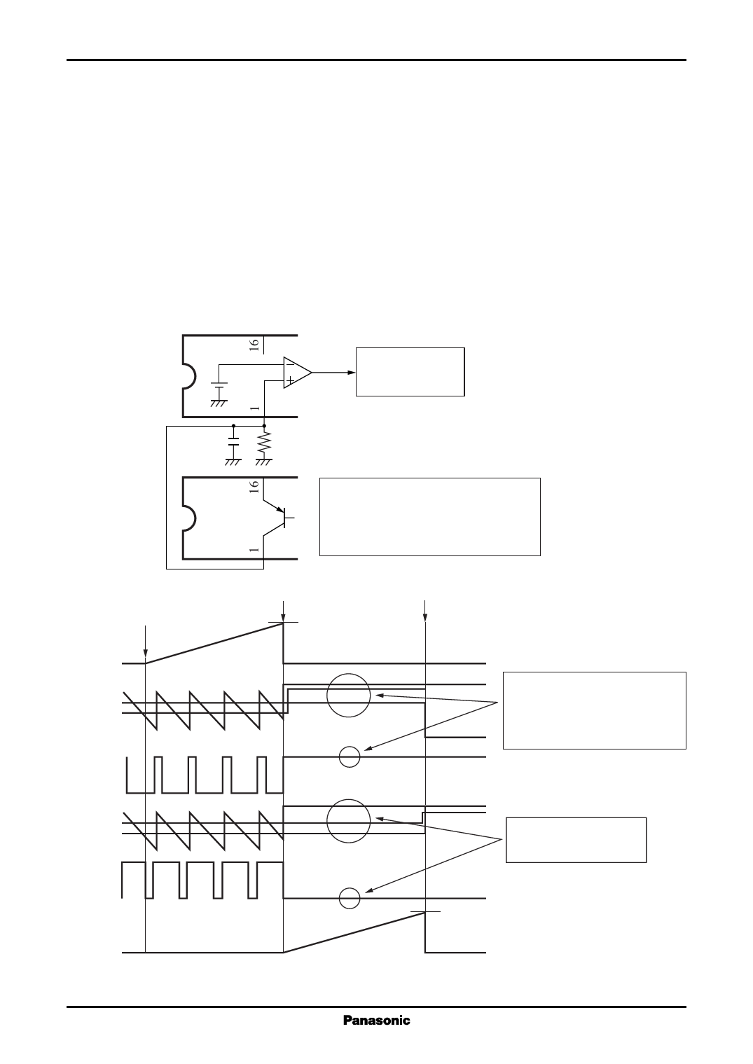
2. About the operation of short-circuit protection at parallel synchronous operation
In the case of the operation in parallel, if the single output (or multiple outputs) of them is short-circuited and
the timer latch short circuit protection of the IC is operated, the output of other ICs will be also shut down, then
enter into latch mode.
In figure 8, if the IC-2 entered timer latch mode, Q1 turns on and the OSC terminal (pin 1) is fixed to
approximately 1.1 V and the oscillator stops.
Then channel 1 of IC-1 becomes low level than the DT1 terminal (pin 6) voltage or high-level voltage (0.9 V)
of the FB1 terminal set by terminal voltage, and then output 2 stops by PWM1 circuit of inside. The channel 2 stops
output 2 by oscillator high-level detection comparator.
And then, the IC-1 becomes short-circuit state and enters latch mode after a certain time.
It becomes the same operation in case of the IC-1 enters latch mode previously.
IC-1
0.9 V
Channel 2 goes off
at high
Oscillator high-level
detection comparator
The IC entering to the lach mode,
IC-2
Q1 turns on and,
Q1
VOSC = VREF − VCE(sat)
= becomes approximately 1.1 V
IC-2 side
IC-2 latch
output short-circuited
1.19 V
IC-1 latch
S.C.P.
OSC
DT1
FB1
Out1
OSC
FB2
DT2
Out2
Since the OSC terminal voltage
becomes higher than
the DT1 terminal voltage,
the Out1 becomes fully off state.
Forced to be in off state
inside the IC
1.19 V
S.C.P.
Figure 8. Operation of short-circuit protection at parallel synchronous operation
18
Share Link: