AD9913(Rev0) Ver la hoja de datos (PDF) - Analog Devices
Número de pieza
componentes Descripción
Fabricante
AD9913 Datasheet PDF : 32 Pages
| |||
AD9913
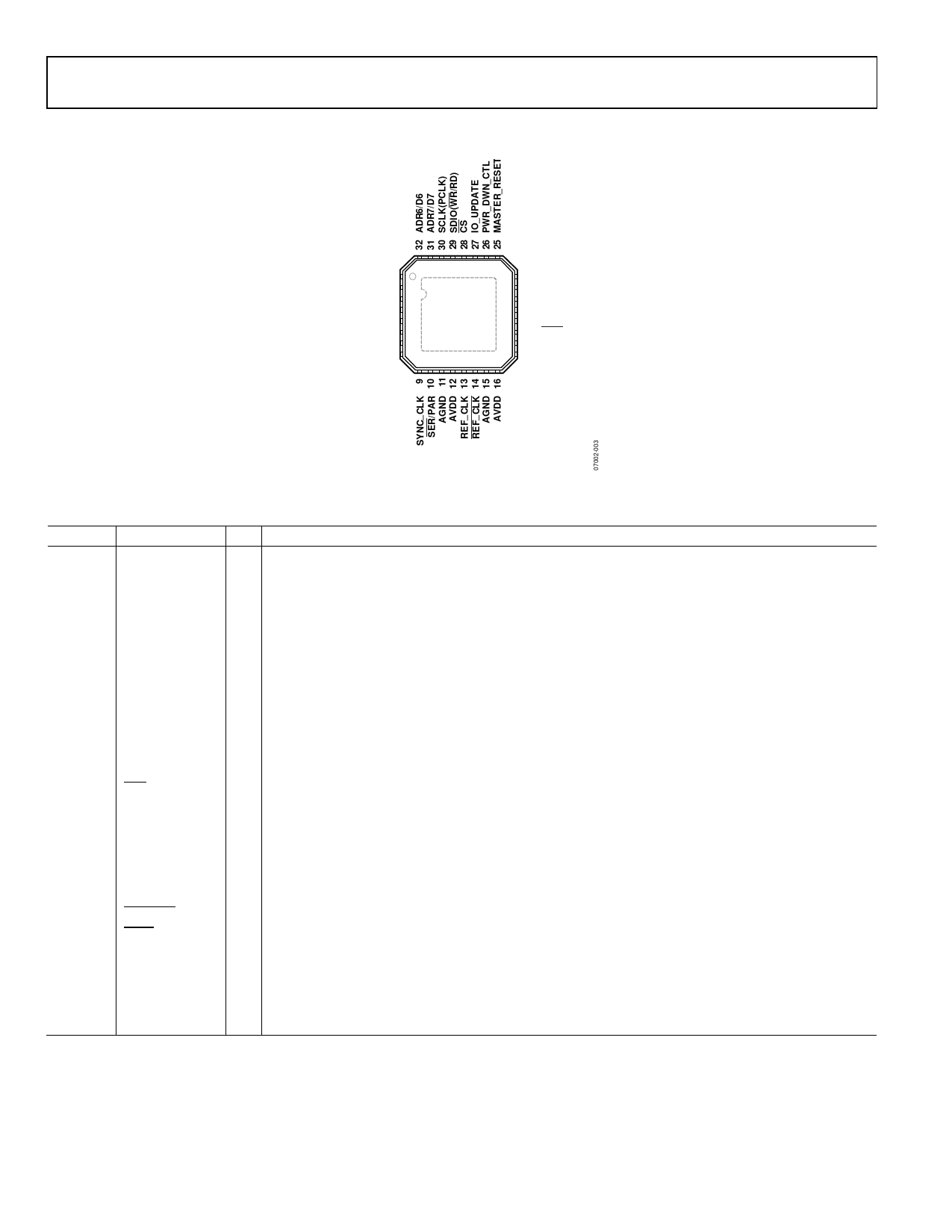
PIN CONFIGURATION AND FUNCTION DESCRIPTIONS
PS2/ADR5/D5 1
PS1/ADR4/D4 2
PS0/ADR3/D3 3
DVDD 4
DGND 5
ADR2/D2 6
ADR1/D1 7
ADR0/D0 8
PIN 1
INDICATOR
AD9913
TOP VIEW
(Not to Scale)
24 RSET
23 AGND
22 AVDD
21 AGND
20 IOUT
19 IOUT
18 AGND
17 AVDD
Figure 3. Pin Configuration
Table 3. Pin Function Descriptions
Pin No. Mnemonic
I/O Description
1
PS2/ADR5/D5 I/O Multipurpose pin: Profile Select Pin (PS2) in Direct Switch Mode, Parallel Port Address Line (ADR5), and
Data Line (D5) to program registers.
2
PS1/ADR4/D4 I/O Multipurpose pin: Profile Select Pin (PS1) in Direct Switch Mode or Linear Sweeping Mode, Parallel Port
Address Line (ADR4), and Data Line (D4) to program registers.
3
PS0/ADR3/D3 I/O Multipurpose pin: Profile Select Pin (PS0) in Direct Switch Mode or Linear Sweeping Mode, Parallel Port
Address Line (ADR3), and Data Line (D3) to program registers.
4
DVDD
I Digital Power Supply (1.8 V).
5
DGND
I Digital Ground.
6
ADR2/D2
I/O Parallel Port Address Line 2 and Data Line 2.
7
ADR1/D1
I/O Parallel Port Address Line 1and Data Line 1.
8
ADR0/D0
I/O Parallel Port Address Line 0 and Data Line 0.
9
SYNC_CLK
O Clock Out. The profile pins [PS0:PS2] and the IO_UPDATE pin (Pin 27) should be set up to the rising
edge of this signal to maintain constant pipe line delay through the device.
10
SER/PAR
I Serial Port and Parallel Port Selection. Logic low = serial mode; logic high = parallel mode.
11, 15,
18, 21,
23
AGND
I Analog Ground.
12, 16,
17, 22
AVDD
I Analog Power Supply (1.8 V).
13
REF_CLK
I Reference Clock Input. See the REF_CLK Overview section for more details.
14
REF_CLK
I Complementary Reference Clock Input. See the REF_CLK Overview section for more details.
19
IOUT
O Open Source DAC Complementary Output Source. Current mode. Connect through 50 Ω to AGND.
20
IOUT
O Open Source DAC Output Source. Current mode. Connect through 50 Ω to AGND.
24
RSET
I Analog Reference. This pin programs the DAC output full-scale reference current. Attach a 4.64 kΩ
resistor to AGND.
25
MASTER_RESET I Master Reset, Digital Input (Active High). This pin clears all memory elements and reprograms registers
to default values.
Rev. 0 | Page 6 of 32
Share Link: 