AAT3685IWP-4.2-1-T1 Ver la hoja de datos (PDF) - Analog Technology Inc
Número de pieza
componentes Descripción
Fabricante
AAT3685IWP-4.2-1-T1 Datasheet PDF : 21 Pages
| |||
BatteryManagerTM
PRODUCT DATASHEET
AAT3685
Lithium-Ion/Polymer Battery Charger
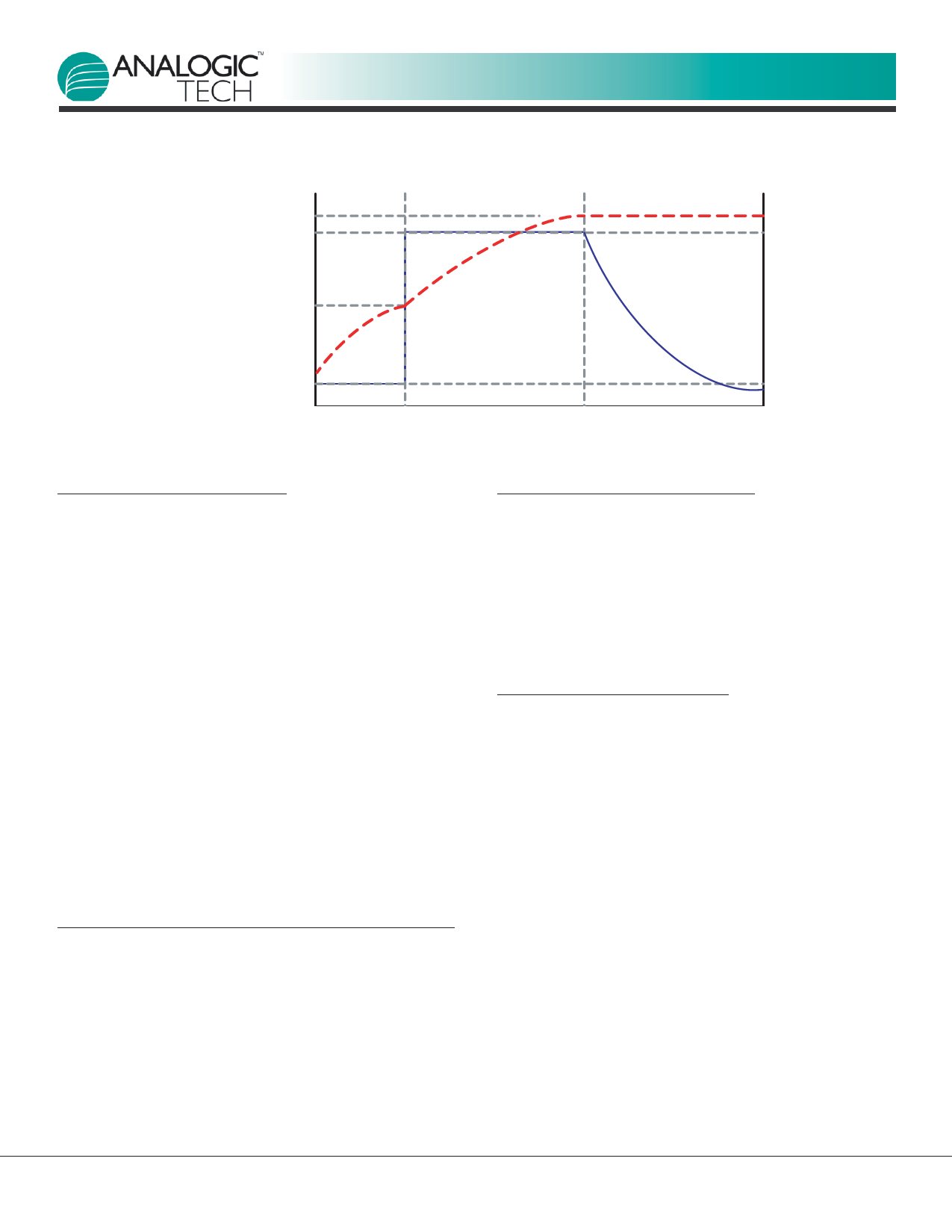
Charge Complete Voltage
Regulated Current
Preconditioning
Trickle Charge
Phase
Constant Current
Charge Phase
I = Max CC
Constant Voltage
Charge Phase
Constant Current Mode
Voltage Threshold
Trickle Charge and I = CC / 10
Termination Threshold
Figure 1: Current vs. Voltage Profile During Charging Phases.
Battery Preconditioning
Before the start of charging, the AAT3685 checks sev-
eral conditions in order to assure a safe charging envi-
ronment. The input supply must be above the minimum
operating voltage, or under-voltage lockout threshold
(VUVLO), for the charging sequence to begin. In addition,
the cell temperature, as reported by a thermistor con-
nected to the TS pin from the battery, must be within the
proper window for safe charging. When these conditions
have been met and a battery is connected to the BAT
pin, the AAT3685 checks the state of the battery. If the
cell voltage is below the Preconditioning Voltage Threshold
(VMIN), the AAT3685 begins preconditioning the cell.
The battery preconditioning trickle charge current is
equal to the fast charge constant current divided by 10.
For example, if the programmed fast charge current is
500mA, then the preconditioning mode (trickle charge)
current will be 50mA. Cell preconditioning is a safety pre-
caution for a deeply discharged battery and also aids in
limiting power dissipation in the pass transistor when the
voltage across the device is at the greatest potential.
Fast Charge / Constant Current Charging
Battery cell preconditioning continues until the voltage
on the BAT pin exceeds the Preconditioning Voltage
Threshold (VMIN). At this point, the AAT3685 begins the
constant current fast charging phase. The fast charge
constant current (ICC) amplitude is determined by the
selected charge mode SETH or SETL and is programmed
by the user via the RSETH and RSETL resistors. The AAT3685
remains in constant current charge mode until the bat-
tery reaches the voltage regulation point, VBAT.
Constant Voltage Charging
The system transitions to a constant voltage charging
mode when the battery voltage reaches output charge
regulation threshold (VBAT) during the constant current,
fast charge phase. The regulation voltage level is fac-
tory programmed to 4.2V ( 1%). The charge current in
the constant voltage mode drops as the battery cell
under charge reaches its maximum capacity.
End of Charge Cycle Termination
and Recharge Sequence
When the charge current drops to 7.5% of the pro-
grammed fast charge current level in the constant volt-
age mode, the device terminates charging and goes into
a sleep state. The charger will remain in a sleep state
until the battery voltage decreases to a level below the
battery recharge voltage threshold (VRCH).
When the input supply is disconnected, the charger will
also automatically enter power-saving sleep mode. Only
consuming an ultra-low 0.3μA in sleep mode (1μA for
AAT3685-1), the AAT3685 minimizes battery drain when
it is not charging. This feature is particularly useful in
applications where the input supply level may fall below
the battery charge or under-voltage lockout level. In
such cases where the AAT3685 input voltage drops, the
device will enter the sleep mode and automatically
resume charging once the input supply has recovered
from its fault condition.
3685.2007.12.1.4
www.analogictech.com
11
Share Link: 