MAX691AD Ver la hoja de datos (PDF) - Maxim Integrated
Número de pieza
componentes Descripción
Fabricante
MAX691AD Datasheet PDF : 16 Pages
| |||
Microprocessor Supervisory Circuits
2.8V
50Ω
OUTPUT
IMPEDANCE
+5V
VBATT VCC
MAX691A
MAX693A
MAX800L
MAX800M
CE IN
CE OUT
GND
CLOAD
2.0V to 5.5V
+5V
VCC
VBATT
MAX691A
MAX693A
PFI
MAX800L
MAX800M
PFO
GND
LOW BATT
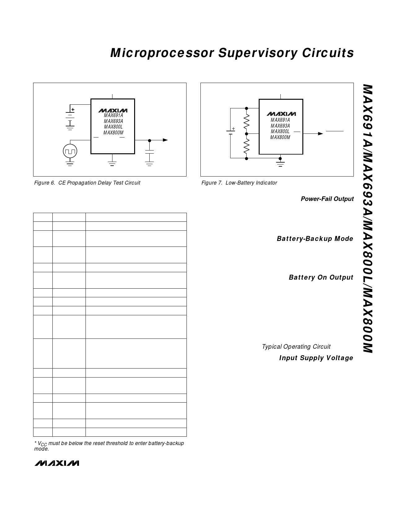
Figure 6. CE Propagation Delay Test Circuit
Figure 7. Low-Battery Indicator
Table 2. Input and Output Status in Battery-Backup
Mode
PIN NAME
STATUS
1
VBATT Supply current is 1µA max.
2
VOUT
VOUT is connected to VBATT through an
internal PMOS switch.
3
VCC
Battery switchover comparator monitors
VCC for active switchover.
4
GND GND 0V, 0V reference for all signals.
5
BATT ON
Logic high. The open-circuit output is
equal to VOUT.
6 LOWLINE Logic low*
7
OSC IN OSC IN is ignored.
8 OSC SEL OSC SEL is ignored.
The power-fail comparator remains
9
PFI
active in the battery-backup mode for
VCC ≥ VBATT - 1.2V typ.
The power-fail comparator remains
10
PFO
active in the battery-backup mode for
VCC ≥ VBATT - 1.2V typ. Below this volt-
age, PFO is forced low.
11
WDI Watchdog is ignored.
12
CE OUT
Logic high. The open-circuit voltage is
equal to VOUT.
13
CE IN High impedance
14
WDO
Logic high. The open-circuit voltage is
equal to VOUT.
15
RESET Logic low*
16
RESET High impedance*
* VCC must be below the reset threshold to enter battery-backup
mode.
Power-Fail Output
The Power-Fail Output (PFO) goes low when PFI goes
below 1.25V. It typically sinks 3.2mA with a saturation
voltage of 0.1V. With PFI above 1.25V, PFO is actively
pulled to VOUT.
Battery-Backup Mode
Two conditions are required to switch to battery-back-
up mode: 1) VCC must be below the reset threshold,
and 2) VCC must be below VBATT. Table 2 lists the sta-
tus of the inputs and outputs in battery-backup mode.
Battery On Output
The Battery On (BATT ON) output indicates the status
of the internal VCC/battery-switchover comparator,
which controls the internal VCC and VBATT switches.
For VCC greater than VBATT (ignoring the small hys-
teresis effect), BATT ON typically sinks 3.2mA at 0.1V
saturation voltage. In battery-backup mode, this termi-
nal sources approximately 10µA from VOUT. Use BATT
ON to indicate battery-switchover status or to supply
base drive to an external pass transistor for higher-cur-
rent applications (see Typical Operating Circuit).
Input Supply Voltage
The Input Supply Voltage (VCC) should be a regulated
5V. VCC connects to VOUT via a parallel diode and a
large PMOS switch. The switch carries the entire cur-
rent load for currents less than 250mA. The parallel
diode carries any current in excess of 250mA. Both the
switch and the diode have impedances less than 1Ω
each. The maximum continuous current is 250mA, but
power-on transients may reach a maximum of 1A.
______________________________________________________________________________________ 11
Share Link: 