MAX691AD Ver la hoja de datos (PDF) - Maxim Integrated
Número de pieza
componentes Descripción
Fabricante
MAX691AD Datasheet PDF : 16 Pages
| |||
Microprocessor Supervisory Circuits
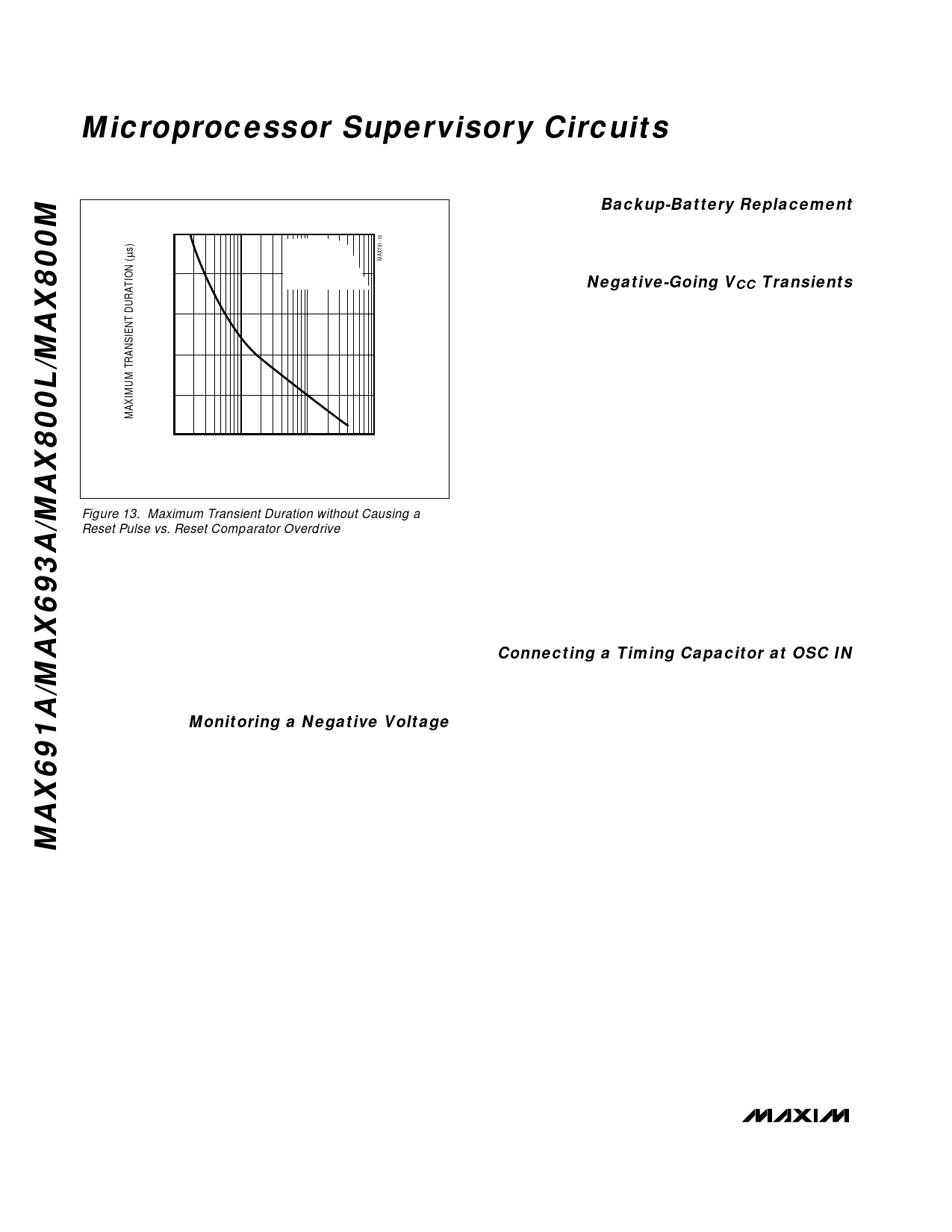
100
VCC = 5V
TA = +25°C
80
0.1µF CAPACITOR
FROM VOUT TO GND
60
40
20
0
10
100
1000
10000
RESET COMPARATOR OVERDRIVE,
(Reset Threshold Voltage - VCC) (mV)
Figure 13. Maximum Transient Duration without Causing a
Reset Pulse vs. Reset Comparator Overdrive
parator. Select the ratio of R1 and R2 such that PFI sees
1.25V when VIN falls to the desired trip point (VTRIP).
Resistor R3 adds hysteresis. It will typically be an order
of magnitude greater than R1 or R2. The current
through R1 and R2 should be at least 1µA to ensure that
the 25nA (max) PFI input current does not shift the trip
point. R3 should be larger than 10kΩ to prevent it from
loading down the PFO pin. Capacitor C1 adds noise
rejection.
Monitoring a Negative Voltage
The power-fail comparator can be used to monitor a
negative supply voltage using Figure 12’s circuit. When
the negative supply is valid, PFO is low. When the neg-
ative supply voltage drops, PFO goes high. This cir-
cuit’s accuracy is affected by the PFI threshold
tolerance, the VCC voltage, and resistors R1 and R2.
Backup-Battery Replacement
The backup battery may be disconnected while VCC is
above the reset threshold. No precautions are neces-
sary to avoid spurious reset pulses.
Negative-Going VCC Transients
While issuing resets to the µP during power-up, power-
down, and brownout conditions, these supervisors are
relatively immune to short-duration, negative-going VCC
transients (glitches). It is usually undesirable to reset
the µP when VCC experiences only small glitches.
Figure 13 shows maximum transient duration vs. reset-
comparator overdrive, for which reset pulses are not
generated. The graph was produced using negative-
going VCC pulses, starting at 5V and ending below the
reset threshold by the magnitude indicated (reset com-
parator overdrive). The graph shows the maximum
pulse width a negative-going VCC transient may typical-
ly have without causing a reset pulse to be issued. As
the amplitude of the transient increases (i.e., goes far-
ther below the reset threshold), the maximum allowable
pulse width decreases. Typically, a VCC transient that
goes 100mV below the reset threshold and lasts for
40µs or less will not cause a reset pulse to be issued.
A 100nF bypass capacitor mounted close to the VCC
pin provides additional transient immunity.
Connecting a Timing Capacitor at OSC IN
When OSC SEL is connected to ground, OSC IN dis-
connects from its internal 10µA (typ) pull-up and is
internally connected to a ±100nA current source.
When a capacitor is connected from OSC IN to ground
(to select alternative reset and watchdog timeout peri-
ods), the current source charges and discharges the
timing capacitor to create the oscillator that controls the
reset and watchdog timeout period. To prevent timing
errors or oscillator start-up problems, minimize external
current leakage sources at this pin, and locate the
capacitor as close to OSC IN as possible. The sum of
PC-board leakage plus OSC capacitor leakage must be
small compared to ±100nA.
14 ______________________________________________________________________________________
Share Link: 