STLC4420A Ver la hoja de datos (PDF) - STMicroelectronics
Número de pieza
componentes Descripción
Fabricante
STLC4420A Datasheet PDF : 40 Pages
| |||
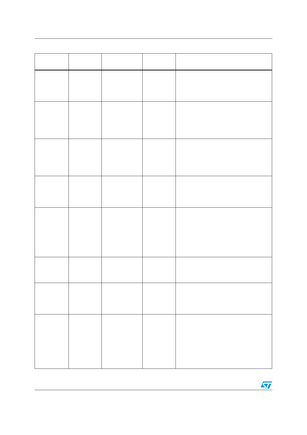
Pin descriptions
STLC4420A
Table 1. STLC4420A signal descriptions (continued)
Pin name Pin number
Type
Internal
resistor
Function
VDD_QLO A4
VDD_VCO A6
Analog supply
input
Analog supply
input
VDD_BIAS N3
Analog supply
input
VDDD
AGND
TX_GND
B15, J22,
M21, N18,
E14, E15,
L13, N9,G16
Digital supply
input
B1-B8,B11,
C4-C13, D3,
E3, F3, F6-
F11,
G6-G11, H6-
H11, J3, L8-
L12, M3, N5,
N6, N8, N11
Analog ground
G1, G2, G3,
H3, J2, K2
Analog ground
VDD_CORE
A23, B21,
C19, E16,
M17, M19,
N21
Digital supply
input
DGND
A17,L14, L15,
L16, M9, K15,
J15, H15,
H19, G19,
F14, F15,
F19, F22,
E22, C22,
E23, N24,
B24, A24
Digital ground
Analog 1.8V supply input for RF Quadrature
Local Oscillator (QLO). Decouple to a solid
-
ground plane using a ceramic capacitor
located as close as possible to the pin. Refer
to evaluation platform schematics.
Analog 1.8V supply input for the RF Voltage
Controlled Oscillator (VCO). Typically
-
connected to V1OUT pin N15. Decouple to a
solid ground plane using a ceramic capacitor
located as close as possible to the pin. Refer
to evaluation platform schematics.
Analog supply input for BIAS control ciruits.
Typically connected to V4OUT pin M16.
-
Decouple to a solid ground plane using a
ceramic capacitor located as close as
possible to the pin. Refer to evaluation
platform schematics.
Digital 1.8V I/O power supply input pins.
Decouple to a solid ground plane using
-
ceramic capacitors located as close a
possible to the appropriate pins. Refer to
evaluation platform schematics.
All AGND pins must be connected together
through a solid ground plane. For optimal
-
performance, refer to the evaluation platform
layout for the proper AGND and DGND
grounding scheme.
All TX_GND pins must be connected together
-
through a solid ground plane. For optimal
performance, refer to the evaluation platform
layout for the proper grounding scheme.
Digital 1.2V core supply. Decouple to a solid
ground plane using ceramic capacitors
-
located as close a possible to the appropriate
pins. Refer to evaluation platform
schematics.
All DGND pins must be connected together
through a common solid ground plane. For
-
maximum performance, refer to the
evaluation platform layout for the proper
AGND and DGND grounding scheme.
10/40
Share Link: 