MAX7031 Ver la hoja de datos (PDF) - Maxim Integrated
Número de pieza
componentes Descripción
Fabricante
MAX7031
Maxim Integrated

MAX7031 Datasheet PDF : 20 Pages
| |||
Low-Cost, 308MHz, 315MHz, and 433.92MHz
FSK Transceiver with Fractional-N PLL
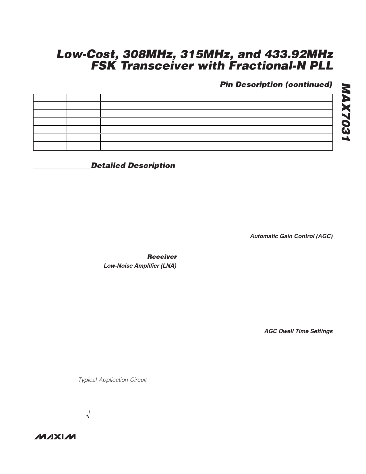
Pin Description (continued)
PIN
NAME
FUNCTION
28
AUTOCAL Enable (Logic-High) to Allow FSK Demodulator Calibration. Bypass to GND with a 10pF capacitor.
29
AGC1 AGC Enable/Dwell Time Control 1. See Table 1. Bypass to GND with a 10pF capacitor.
30
AGC0 AGC Enable/Dwell Time Control 0 (LSB). See Table 1. Bypass to GND with a 10pF capacitor.
31
XTAL1 Crystal Input 1. Bypass to GND if XTAL2 is driven by an AC-coupled external reference.
32
XTAL2 Crystal Input 2. XTAL2 can be driven from an external AC-coupled reference.
—
EP
Exposed Pad. Solder evenly to the board’s ground plane for proper operation.
Detailed Description
The MAX7031 308MHz, 315MHz, and 433.92MHz
CMOS transceiver and a few external components pro-
vide a complete transmit and receive chain from the
antenna to the digital data interface. This device is
designed for transmitting and receiving FSK data. All
transmit frequencies are generated by a fractional-N-
based synthesizer, allowing for very fine frequency
steps in increments of fXTAL/4096. The receive local
oscillator (LO) is generated by a traditional integer-N-
based synthesizer. Depending on component selec-
tion, data rates as high as 33kbps (Manchester
encoded) or 66kbps (NRZ encoded) can be achieved.
Receiver
Low-Noise Amplifier (LNA)
The LNA is a cascode amplifier with off-chip inductive
degeneration that achieves approximately 30dB of volt-
age gain that is dependent on both the antenna-match-
ing network at the LNA input, and the LC tank network
between the LNA output and the mixer inputs.
The off-chip inductive degeneration is achieved by con-
necting an inductor from LNASRC to AGND. This induc-
tor sets the real part of the input impedances at LNAIN,
allowing for a more flexible match for low-input imped-
ances such as a PCB trace antenna. A nominal value
for this inductor with a 50Ω input impedance is 12nH at
315MHz and 10nH at 434MHz, but the inductance is
affected by PCB trace length. LNASRC can be shorted
to ground to increase sensitivity by approximately 1dB,
but the input match must then be reoptimized.
The LC tank filter connected to LNAOUT consists of L5
and C9 (see the Typical Application Circuit). Select L5
and C9 to resonate at the desired RF input frequency.
The resonant frequency is given by:
f=
1
2π LTOTAL × CTOTAL
where LTOTAL = L5 + LPARASITICS and CTOTAL = C9 +
CPARASITICS.
LPARASITICS and CPARASITICS include inductance and
capacitance of the PCB traces, package pins, mixer
input impedance, LNA output impedance, etc. These
parasitics at high frequencies cannot be ignored, and
can have a dramatic effect on the tank filter center fre-
quency. Lab experimentation should be done to opti-
mize the center frequency of the tank. The parasitic
capacitance is generally 5pF to 7pF.
Automatic Gain Control (AGC)
When the AGC is enabled, it monitors the RSSI output.
When the RSSI output reaches 1.28V, which corre-
sponds to an RF input level of approximately -55dBm,
the AGC switches on the LNA gain-reduction attenua-
tor. The attenuator reduces the LNA gain by 36dB,
thereby reducing the RSSI output by about 540mV to
740mV. The LNA resumes high-gain mode when the
RSSI output level drops back below 680mV (approxi-
mately -59dBm at the RF input) for a programmable
interval called the AGC dwell time (see Table 1). The
AGC has a hysteresis of approximately 4dB. With the
AGC function, the RSSI dynamic range is increased.
AGC is not necessary for most FSK applications.
AGC Dwell Time Settings
The AGC dwell timer holds the AGC in a low-gain state
for a set amount of time after the power level drops
below the AGC switching threshold. After that set
amount of time, if the power level is still below the AGC
threshold, the LNA goes into high-gain state.
______________________________________________________________________________________ 11
Share Link: