MAX6972 Ver la hoja de datos (PDF) - Maxim Integrated
Número de pieza
componentes Descripción
Fabricante
MAX6972 Datasheet PDF : 23 Pages
| |||
16-Output PWM LED Drivers
for Message Boards
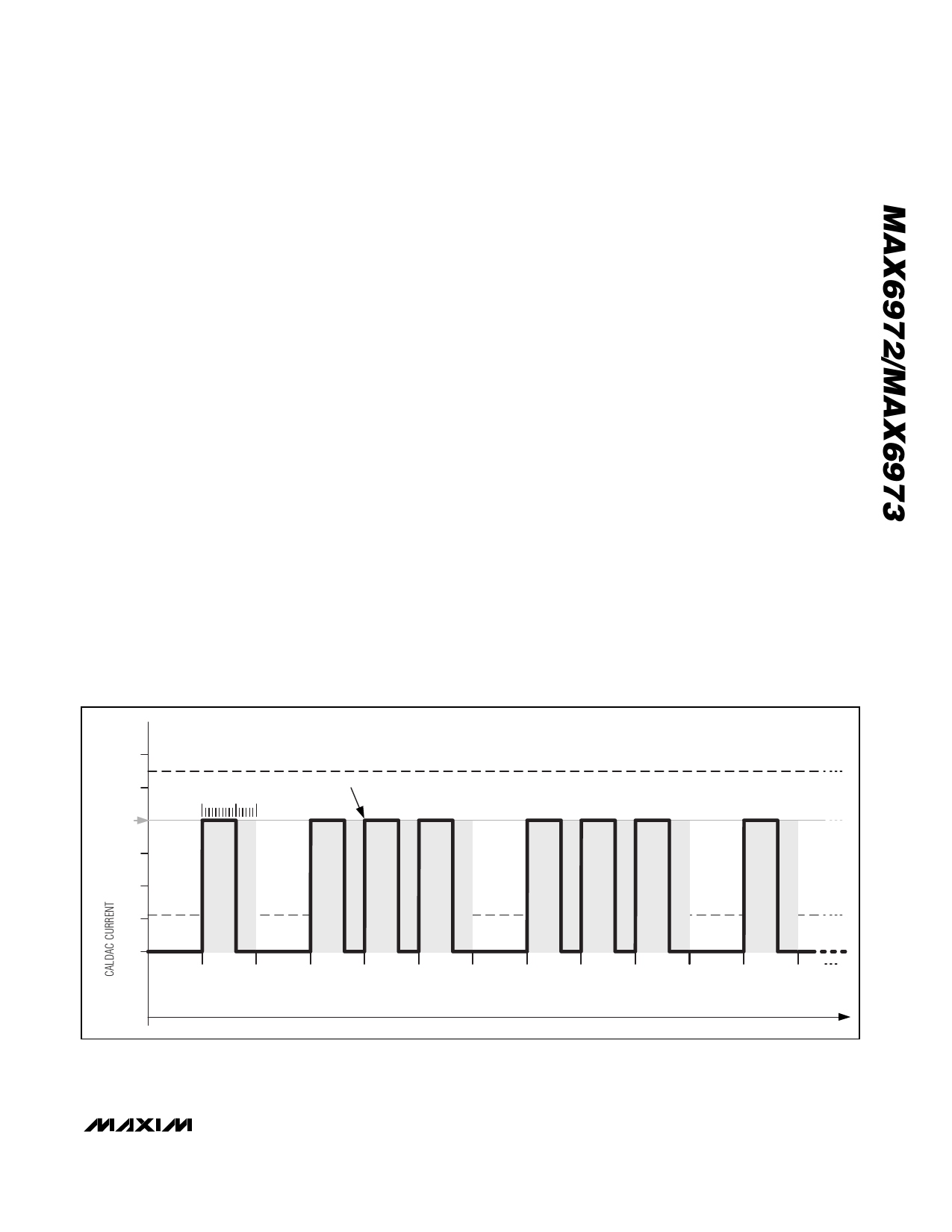
The global-intensity PDM value is set to 96DEC, producing
an even distribution of ON subframes out of the 128 pos-
sible (shown in Figure 4 as subframes 1, 3, 4, 5, etc).
Each subframe can be ON for a PWM duration set by the
individual PWM value. The PWM value setting of
2560DEC out of 4096 (12-bit) results in a further reduction
of current ON time (shown in bold trace).
The internal PDM logic spreads the on subframes as
evenly as possible among the off subframes to keep
the effective scanning frequency high.
For applications with a slower clock speed, the
MAX6973 can increase the display refresh rate by a
factor of four to eliminate visible flicker. Setting configu-
ration bit D4 (GLB4) to 1 activates the increased
refresh rate (see Table 6). The increased refresh rate
reduces the number of global-intensity settings by a
factor of four (see Table 3).
MAX6972 Video-Frame Timing
The MAX6972 supports up to 60 video frames per
second (fps). The following equation shows the
required clock frequency to support 60 video fps:
60 (video fps) x 4096 (clocks per 12-bit PWM period) x
128 (global-intensity subframes) = 31.5MHz.
The MAX6972 supports up to a 33MHz clock signal
(~63fps).
Each 12-bit PWM period contains 4096 clock cycles;
multiply that number by 128 (number of global intensity
subframes) to obtain the required number of clock cycles
(524,288) per video frame. The MAX6972 requires 36
bits (12 bits per color multiplied by three colors) to drive
an RGB pixel. The maximum pixel data that the
MAX6972 can send per video frame is 524,288 / 36 or
14,563 pixels, corresponding to 2730 cascaded
MAX6972s.
MAX6973 Video-Frame Timing
The MAX6973 also supports up to 60 video frames per
second (fps). The following equation shows the
required clock frequency to support 60 video fps:
60 (video fps) x 16,384 (clocks per 14-bit PWM period)
x 32 (global-intensity subframes) = 31.5MHz.
The MAX6973 supports up to a 33MHz clock signal
(~63fps).
Each 14-bit PWM period contains 16,384 clock cycles;
multiply 16,384 by 32 (global-intensity subframes) to
obtain the required number of clock cycles (524,288)
per video frame. The MAX6973 requires 42 bits (14 bits
per color multiplied by three colors) to drive an RGB
pixel. The maximum pixel data that the MAX6973 can
send per video frame is 524,288 / 42 or 12,483 pixels,
corresponding to 2340 cascaded MAX6973s.
(mA)
55mA MAX
50
PWM = 2560/4096
169d = 40
OUTPUT LED CURRENT
GLOBAL PDM = 96/128 SUBFRAMES
30
20
11mA MIN
10
ON
0
1
ON
ON
ON
2
3
4
5
ON
ON
ON
6
7
8
9
ONE FRAME IS 219 (524,288) CLKI CYCLES LONG
SUBFRAME NUMBER
ON
10
11
Figure 4. The three levels of LED current control (CALDAC, global-intensity PDM, and individual PWM) modulate the average output
current.
______________________________________________________________________________________ 11
Share Link: 