UT553B-RTIGCX Ver la hoja de datos (PDF) - Aeroflex UTMC
Número de pieza
componentes Descripción
Fabricante
UT553B-RTIGCX Datasheet PDF : 52 Pages
| |||
Perform a hardware reset by asserting the MRST input pin
for a minimum of 500ns. During reset negate the EXT TEST
pin (i.e., logic low); assertion of the EXT TEST pin forces
the RTI to enter the external self-test mode of operation.
Software reset the RTI by simultaneously applying a logic
zero to input pins CS, RD/WR, and CTRL while the least
significant bit of the address input bus is a logic one (ADDR
IN (0)=0).
1.8 Encoder and Decoder
The RTI interfaces directly to a bus transmitter/receiver via
the RTI Manchester II encoder/decoder. The UT1553B RTI
receives the command word from the MIL-STD-1553B bus
and processes it either by the primary or secondary decoder.
Each decode checks for the proper sync pulse and
Manchester waveform, edge skew, correct number of bits,
and parity. If the command is a receive command, the RTI
processes each incoming data word for correct word count
and contiguous data. If an invalid message error is detected,
the message error pin is asserted, the RTI ceases processing
the remainder (if any) of the message, and it then suppresses
status word transmission. Upon command validation
recognition, the external status outputs are enabled.
Reception of illegal commands does not suppress status
word transmission.
A timer precludes transmission greater than 730ms by the
assertion of fail-safe timer (TIMERON). This timer is reset
upon receipt of another valid command.
1.9 Illegal Command Decoding
The host has the option of asserting the ILL COMM pin to
illegalize a received command word. On receipt of an illegal
command, the RTI sets the message error bit in the status
word, sets the Message Error output, and sets the message
error latch in the System Register.
Use the following RTI outputs to externally decode an
illegal command, Mode Code or Subaddress indicator (MC/
SA), Mode Code or Subaddress bus MCSA(4:0), Command
Strobe (COMSTR), Broadcast (BRDCST), etc. (See figure
6 pages 11-12).
To illegalize a transmit command the ILL COMM pin is
asserted 3.3ms after STATUS goes to a logic one. Assertion
of the ILL COMM pin within 3.3ms allows the RTI to
respond with the Message Error bit of the outgoing status
word at a logic one.
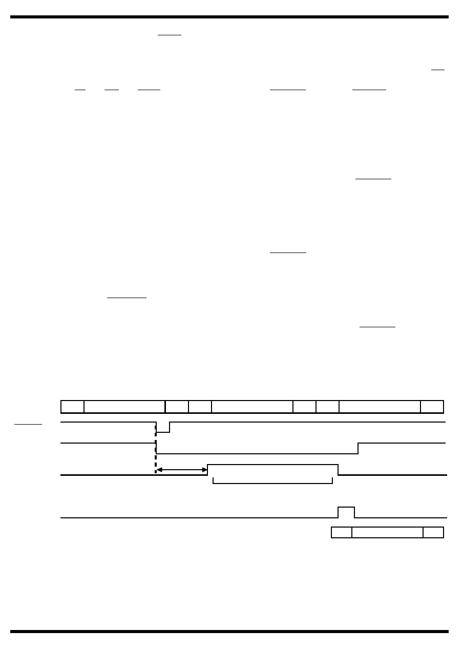
For an illegal receive command, the ILL COMM pin is
asserted within 18.2ms after the COMSTR transitions to a
logic zero in order to suppress data words from being stored
(suppress DMARQ assertions). In addition, the ILL COMM
pin must be at a logic one throughout the reception of the
message until STATUS is asserted.
If the illegal command is mode code 2, 4, 5, 6, 7, or 18,
assert the ILL COMM pin within 664ns after Command
Strobe (COMSTR) transitions to logic zero. Asserting the
ILL COMM pin within the 664 nanoseconds inhibits the
mode code function.
The above timing conditions also apply when the host
externally decodes an illegal broadcast command. The host
must remove the illegal command condition so that the next
command is not falsely decoded as illegal. These
requirements are easily met if the COMSTR output is used
to qualify the ILL COMM input to the RTI.
BIPHASE IN CS COMMAND WORD
P DS
DATA WORD
P DS
DATA WORD
P
COMSTR
RCV
ILL COMM
18.2µs
DMA Activity Suppressed
STATUS
BIPHASE OUT
SS
STATUS WORD
P
Note:
1. Illegalcommandcondition;statuswordMessageErrorbitsettologicone,RTIMESERRpinsettoalogicone, RTIStatusRegisterMessage
Error bit set to logic one.
Figure 6a. Illegal Receive Command Decoding
RTI-11
Share Link: 