MC14560B Ver la hoja de datos (PDF) - Motorola => Freescale
Número de pieza
componentes Descripción
Fabricante
MC14560B Datasheet PDF : 13 Pages
| |||
The truth table and Karnaugh maps for sign, overflow, and
End Around Carry are shown in Figures 6 and 7. Note the
use of BS′ from the exclusive–OR of Add/Sub and BS. BS′
eliminates Add/Sub as a variable in the truth table. As an ex-
ample of truth table generation, consider an n decade adder/
subtracter where AS = “0”, BS = “1”, and Add/Sub = “0”. B is
v in 9’s complement form, 10N – 1 – B. Thus A + (10N – 1 – B)
= 10N – 1 + (A – B). There is no carry when A B, and the
sign is negative (sign = “1”). When AS and BS are opposite
states and Add/Sub is a “0” (add mode), no overflow can oc-
cur (overflow = “0”). The other output states are determined
in a similar manner (see Figure 6).
From the Karnaugh maps it is apparent that End Around
Carry is composed of the two symmetrical functions S2 and
S3 of three variables with AS BS′ Cout as the center of sym-
metry. This is the definition of the majority logic function
M3(ABC). Similarly the Sign is composed of the symmetrical
functions S2(3) and S3(3) but with the center of symmetry
translated to ASBS′ Cout. This is equivalent to the majority
function M3(ASBS′ Cout). Further evaluation of the maps and
truth table reveal that Overflow can be generated by the
exclusive–OR function of End Around Carry and Carry Out.
This analysis results in a minimum device count consisting of
one exclusive–OR package and one dual Majority Logic
package to implement BS′, EAC, Sign and Overflow. The
logic connections of these devices are shown in Figure 5.
The output sign, RS, complements the result of the add/
subtract operation when RS = “1”. This is required because
the adder performs 9’s complement arithmetic. Complement-
ing, when RS indicates the result is negative, restores sign
and magnitude convention.
Several variations of the adder/subtracter are possible.
For example, 9’s complement is available at the output of the
NBCD adders, and output complementers are eliminated if
sign and magnitude output is not required.
A
B
A1 A2 A3 A4
VDD C
C
MC14561
Z
F1 F2 F3 F4
A1 A2 A3 A4
B1 B2 B3 AB
Cn
Cin
MC14560
Cout
S1 S2 S3 S4
FROM Cout
VDD
OF MOST SIGNIFICANT
DECADE
A1 A2 A3 A4
C
C
MC14561
Z
F1 F2 F3 F4
Cn + 1
RESULT, R
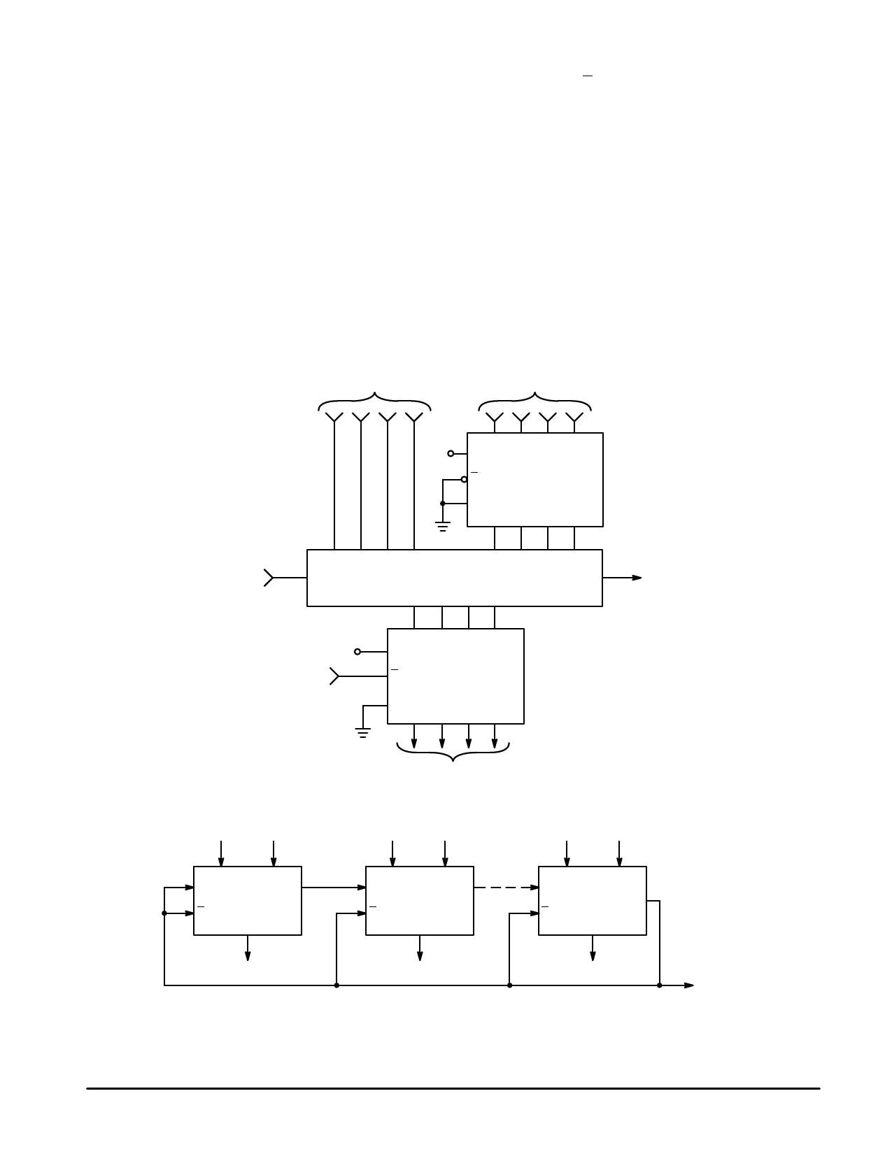
(a) Basic Subtracter Block
LEAST
SIGNIFICANT
DECADE
A1
B1
Cin
BASIC
SUBTRACT
Cout
C BLOCK
R1
A2
Cin
C
B2
An
MOST
SIGNIFICANT
DECADE
Cout
Cin
C
Bn
Cout
R1
R2
Rn
Typical Subtract Time = 0.6 + 0.4n µs where n = Number of Decades
(b) n–Decade Subtracter
Figure 6. Subtraction of Unsigned NBCD Numbers
MOTOROLA CMOS LOGIC DATA
“0” INDICATES
UNDERFLOW
(NEGATIVE RESULT)
MC14560B
7
Share Link: 