L9907N Ver la hoja de datos (PDF) - STMicroelectronics
Número de pieza
componentes Descripción
Fabricante
L9907N Datasheet PDF : 8 Pages
| |||
L9907N
An external resistor RCF is recommended be-
tween the slider of the control and feedback po-
tentiometer.
This resistor assures that in the case of input con-
trol or input feedback wire interruption the input
differential voltage will be within the NEUTRAL
ZONE and the motor position remains frozen.
The circuit features an overvoltage disable func-
tion referred to the supply voltage VS higher than
18V, both outputs are forced to tristate in this con-
dition.
The thermal overload function disables the out-
puts (tristate) when the junction temperature in-
creases above the thermal shutdown threshold
temperature of min. 150°C.
For the start of a heavy loaded motor, if the motor
current reaches the max. value it is necessary to
respect the dynamical thermal resistance junction
to ambient. The maximum output current is 0.8A.
The maximum junction temperature in this phase
should not increase above the thermal shutdown
threshold. In case of output disable due to ther-
mal overload the output remains disabled till the
junction temperature decreases under the thermal
enable threshold. This behaviour is assured with
the thermal shutdown hysteresis threshold , which
minimum value is 20°C.
Figure 3, 5 and 7 show typical application dia-
grams for headlight adjustment applications. To
assure the safety of the circuits in the reverse bat-
tery condition a reverse protection diode D1, is
necessary.
The input currents in this condition are limited by
the resistors RINC and RINF. The transient protec-
tion diode D2 must assure that the maximum rat-
ing for VS during the transients at VBAT line will be
limited to a value lower than absolute maximum
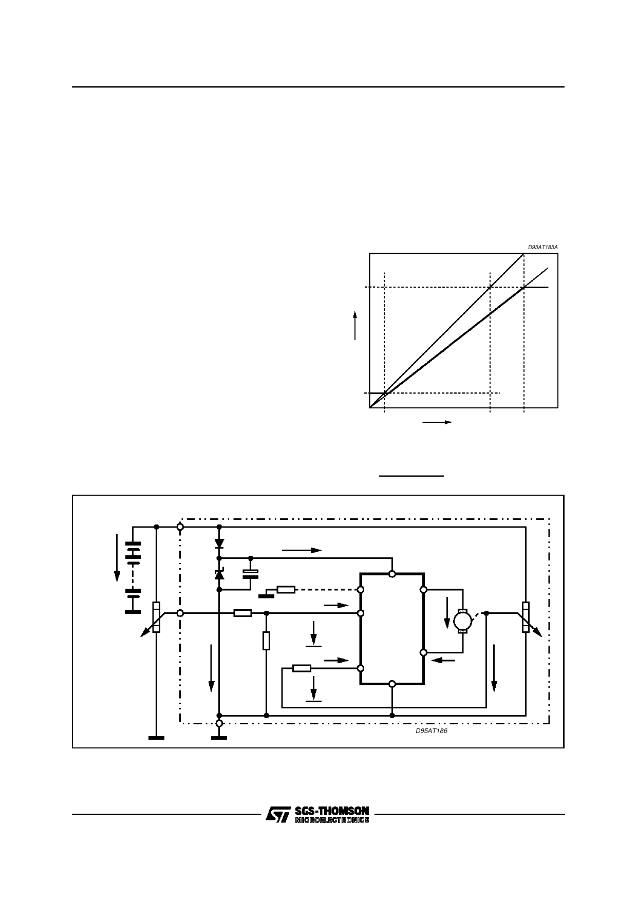
Figure 4: Control to feedbacktransfer characteristic
for proportionalregulation with extended
VC operating range:
VBAT
D95AT185A
VS -2V
VF
1.5V
0
1.5V
VC
VS -2V VBAT
Figure 5: RecommendedApplication Circuit Diagram with L9907Nfor proportionalregulation with extended
VC operating range. For ideal adjusted condition
VF
=
RINC2
RINC1 + RINC2
⋅
VC:
MODULE
VBAT
D1
IQ
D2
CS RPR
VS
PR
OUT C
RINC1
IINC
RF
RC
RINC2
VINC
INC L9907N VM M
OUT F
VC
RINF IINF
INF
IM
VF
VINF
GND
D95AT186
Note:
Recommended value of RINC, RINF (equivalent input resistance to INC and INF) is 5KΩ to 10KΩ. If the motor should not change its position, when
the control signal wire become open, RINC1 and RINC2 should be rated so that VINC ≤ 0.4V in this condition.
5/8
Share Link: 