MAS281C Ver la hoja de datos (PDF) - Dynex Semiconductor
Número de pieza
componentes Descripción
Fabricante
MAS281C Datasheet PDF : 55 Pages
| |||
MAS281
after SYNCN goes low to indicate the start of a new machine
cycle and remains valid until a new SYNCN cycle is begun,
RD/WN is placed in the high impedance state during DMA and
Hold cycles.
2.2.7 MEMORY/INPUT-OUTPUT (M/IO)
Output/Hi-Z, This dual function signal indicates the type of
transfer of the AD bus that is occurring. A high state identifies
memory transfers. A low state identifies l/O transfers. M/ION
goes valid shortly after SYNCN goes low to indicate the start of
a new machine cycle and remains valid until a new SYNCN
cycle is begun. M/ION is placed in the high impedance state
during DMA and Hold cycles and is held high during internal
(non-XIO) operations.
2.2.9 ADDRESS/DATA BUS (AD00 - AD15)
Input/Output/Hi-Z. AD00 through AD15 comprise a
bidirectional multiplexed address and data bus which serves
both as the communication path between the external system
and module as well as the communication path among the
three chips on the module. It is important to note that the AD
bus is shared between the external system and internal
module resources. To avoid bus contention during internal
operations, the AD bus must be isolated from the external
system through the use of a bus transceiver. A data direction
signal (DDN) is provided for transceiver control .
Addresses, data and commands appearing on the AD bus
are represented in positive logic. A high level indicates a logic
1 and a low level indicates a logic 0. AD00 is the most
significant bit position whilst AD15 is the least significant bit
position. The AD bus is placed in the high impedance state
during the data portion of a read SYNCN cycle as well as
during DMA and Hold cycles.
2.2.10 READY (RDY)
This asynchronous active low input is used by the EU state
sequencer, in conjunction with the internal ready signal, to
determine when the current machine cycle may be completed.
By holding RDYN high, wait states may be inserted, stretching
out the current machine cycle and allowing slower devices
sufficient time to complete their operations.
[Note: If RDYN is held high during two consecutive TCLK
high-to-low transitions (with DSN low), a bus timeout fault will
occur and will be indicated in the appropriate bit in the fault
register. The occurrence of this fault will cause the EU state
sequencer to terminate the current machine cycle, drop
SYNCN low, and begin a new machine cycle. Also, the
presently executing macroinstruction will be aborted and
execution will branch, unless masked, to the machine error
interrupt (level 1) software routine. The DTON signal may be
used to override this feature.]
2.2.11 CONTROL DIRECTION (CD)
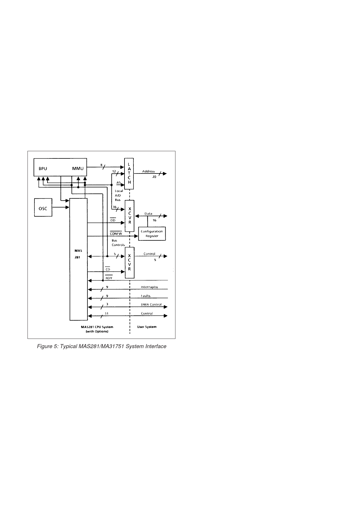
Figure 5: Typical MAS281/MA31751 System Interface
This active low output goes high to indicate the module is
driving the AS, DSN, M/ION, RD/WN and IN/OPN signals.
During DMA and Hold cycles, this signal goes low to indicate
the module has relinquished control of these signals and has
placed them in the high impedance state. The DMA or Console
controller, respectively, may then drive these signals. This
signal should be used to control the transfer direction of the
control signal transceiver.
2.2.8 INSTRUCTION/OPERAND (IN/OP)
2.2.12 DATA DIRECTION (DD)
Output/Hi-Z. This dual function signal indicates the type of
data on the AD bus during the data portion of a SYNCN cycle.
A high state identifies an instruction while a low state identifies
an operand. IN/OPN goes valid shortly after SYNCN goes low
to indicate the start of a new SYNCN cycle and remains valid
until a new SYNCN cycle is begun. This signal is required
during expanded memory accesses. IN/OPN is placed in the
high impedance state during DMA and Hold cycles.
This active low signal indicates the direction of data
transfer on the AD bus. This signal goes high to indicate a write
transfer from the module to the external system. It also goes
high during all internal module operations. DDN goes low to
indicate a read transfer from the external system to the
module. It also goes low during DMA and Hold cycles as well
as during configuration register reads.
[Note: In addition to going high during the execution of
internally implemented XIO commands, DDN also goes high
7/55
Share Link: 