SLA7044 Ver la hoja de datos (PDF) - Allegro MicroSystems
Número de pieza
componentes Descripción
Fabricante
SLA7044 Datasheet PDF : 8 Pages
| |||
SLA7042M AND SLA7044M
MICROSTEPPING,
UNIPOLAR PWM, HIGH-CURRENT
MOTOR CONTROLLER/DRIVERS
REGULATING THE PWM OUTPUT CURRENT
The output current (and motor coil current) waveform
is illustrated in Figure 1. Setting the maximum PWM
current trip point to meet the specified full-step running
current for the motor, IOUT max (DATA input = 111X =
100% ratio), requires only a current-sensing resistor, RS,
and an input reference voltage, VREF/EN, between 0.4 V
and 2.5 V.
IOUT max
≈
VREF/EN
3 • RS
PHASE A
0
PHASE A
I OUT
Dwg. WK-001
FIGURE 1.␣ PHASE A COIL CURRENT WAVEFORM
SERIAL DATA INPUT ENABLE
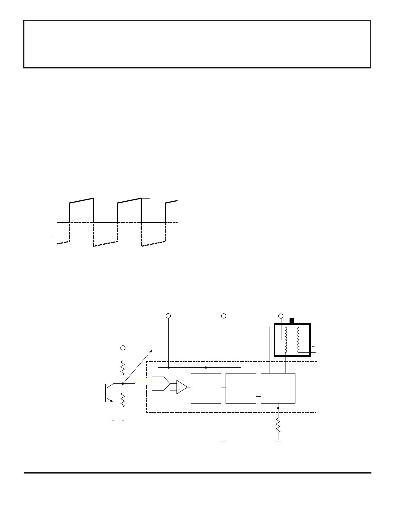
In a minimum-component application, a voltage divider
provides VREF/EN and an npn transistor provides the
required pull-down to enable the serial data input as
shown in Figure 2.
IOUT max ≈
R2
R1 + R2
•
Vb
3 • RS
µP STEPPER MOTOR CONTROL
Alternative REFERENCE/ENABLE input configura-
tions provide for more complete motor control. A tri-state
logic element and a voltage divider allows a fixed refer-
ence voltage, with both output disable and data enable
functions. Complete µP control is usually accomplished
with a D/A converter as shown in Figure 3. Here, digital
control provides an output disable (>VDD - 1 V), VREF, and
VEN (<2.5 V).
ENABLE
DATA
SERIAL DATA
VDD
V BB
B
Vb
TO CHANNEL B
R1
VREF/EN
D/A
R2
B
PWM
OFF-TIME
CONTROL
Ø
CONTROL
LOGIC
A
A
DRIVE
SENSE
RS
FIGURE 2.␣ PWM CONTROL (RUN MODE)
Dwg. EK-011
Share Link: 