STK672-040(2000) Ver la hoja de datos (PDF) - SANYO -> Panasonic
Número de pieza
componentes Descripción
Fabricante
STK672-040
(Rev.:2000)
(Rev.:2000)
SANYO -> Panasonic

STK672-040 Datasheet PDF : 19 Pages
| |||
STK672-040
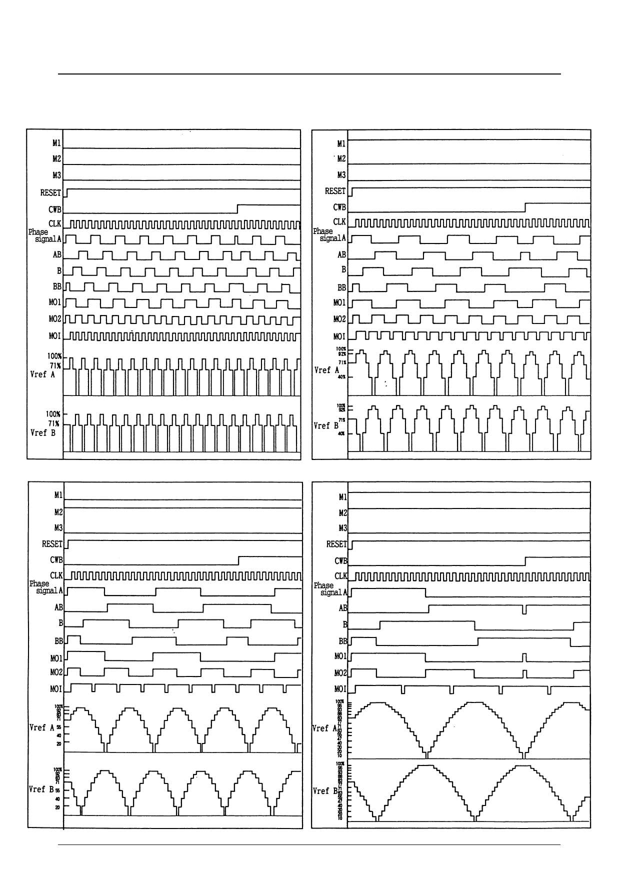
• M1, M2, and M3 (Excitation mode and CLK input edge timing selection)
Pin circuit type: Built-in pull-up resistor (20 kΩ, typical) CMOS Schmitt trigger structure
Function:
M2
M1
M3
1
0
0
0
2 phase excitation
1-2 phase excitation
0
1
1
1
0
1
1-2 phase excitation W1-2 phase excitation 2W1-2 phase excitation
W1-2 phase excitation 2W1-2 phase excitation 4W1-2 phase excitation
Phase switching clock edge timing
Rising edge only
Rising and falling edges
Valid mode setting timing: Applications must not change the mode in the period 5 µs before or after a CLK signal rising
or falling edge.
Mode Setting Acquisition Timing
CLK input
System clock
Mode setting
M1 to M3
Mode switching clock
Hybrid IC internal setting state
Mode switching timing
Phase excitation clock
• M4 and M5 (Microstepping mode rotation vector locus setting)
M4
1
0
1
0
M5
1
0
0
1
Mode Circular
See page 10 for details on the current division ratio.
Excitation counter up/down
A06846
Phase B
1
2
Circular
3
Phase A
A06847
• RESET (Resets all parts of the system.)
Pin circuit type: Built-in pull-up resistor (20 kΩ, typical) CMOS Schmitt trigger structure
Function:
—All circuit states are set to their initial values by setting the RESET pin low. (Note that the pulse width must be at
least 10 µs.)
At this time, the A and B phases are set to their origin, regardless of the excitation mode. The output current goes to
about 71% after the reset is released.
Notes: When power is first applied to this hybrid IC, Vref must be established by applying a reset. Applications must
apply a power on reset when the VCC2 power supply is first applied.
• Vref (Sets the current level used as the reference for constant-current detection.)
Pin circuit type: Analog input structure
Function:
—Constant-current control can be applied to the motor excitation current at 100% of the rated current by applying a
voltage less than the control system power supply voltage VCC2 minus 2.5 V.
—Applications can apply constant-current control proportional to the Vref voltage, with this value of 2.5 V as the
upper limit.
No. 5227-10/19
Share Link: