ESD5Z12T1 Ver la hoja de datos (PDF) - ON Semiconductor
Número de pieza
componentes Descripción
Fabricante
ESD5Z12T1 Datasheet PDF : 4 Pages
| |||
ESD5Z2.5T1 SERIES
ELECTRICAL CHARACTERISTICS
(TA = 25°C unless otherwise noted)
Symbol
Parameter
IPP
VC
VRWM
IR
VBR
IT
IF
VF
Ppk
C
Maximum Reverse Peak Pulse Current
Clamping Voltage @ IPP
Working Peak Reverse Voltage
Maximum Reverse Leakage Current @ VRWM
Breakdown Voltage @ IT
Test Current
Forward Current
Forward Voltage @ IF
Peak Power Dissipation
Max. Capacitance @VR = 0 and f = 1 MHz
I
IF
VC VBR VRWM
IIRT VF
V
IPP
Uni−Directional TVS
ELECTRICAL CHARACTERISTICS (TA = 25°C unless otherwise noted, VF = 0.9 V Max. @ IF = 10 mA for all types)
Device**
ESD5Z2.5T1, G*
Device
Marking
ZD
VRWM
(V)
Max
2.5
IR (mA)
@ VRWM
Max
6.0
VBR (V) @ IT
(Note 2)
Min
4.0
VC (V)
VC (V)
IT @ IPP = 5.0 A† @ Max IPP† IPP (A)†
mA
Typ
Max
Max
1.0
6.5
10.9
11.0
Ppk
(W)†
Max
120
ESD5Z3.3T1, G* ZE
3.3
0.05
5.0
1.0
8.4
14.1
11.2
158
ESD5Z5.0T1, G* ZF
5.0
0.05
6.2
1.0
11.6
18.6
9.4
174
ESD5Z6.0T1, G* ZG
6.0
0.01
6.8
1.0
12.4
20.5
8.8
181
ESD5Z7.0T1, G* ZH
7.0
0.01
7.5
1.0
13.5
22.7
8.8
200
ESD5Z12T1, G*
ZM
12
0.01
14.1
1.0
17
25
9.6
240
* The “G’’ suffix indicates Pb−Free package available.
**Other voltages available upon request.
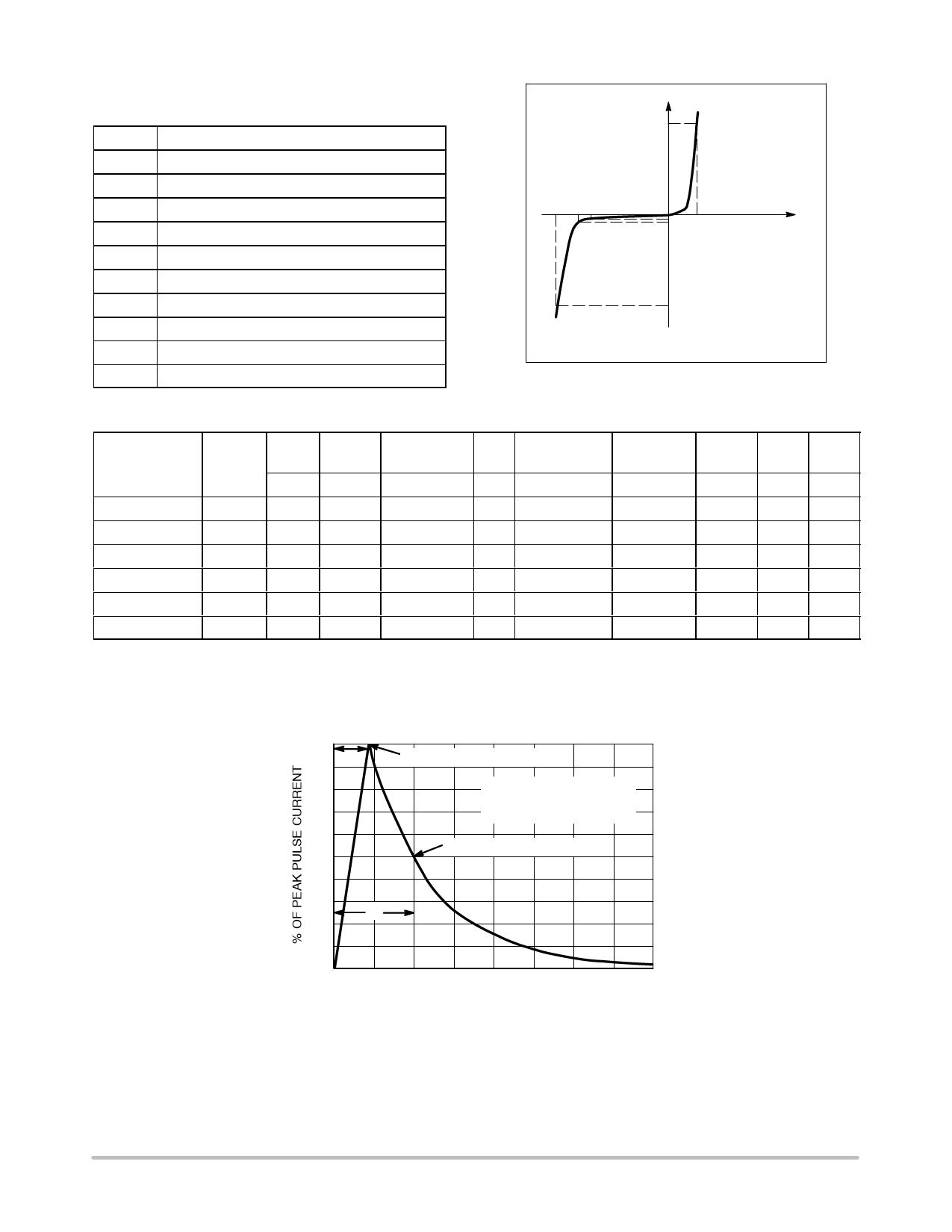
†Surge current waveform per Figure 1.
2. VBR is measured with a pulse test current IT at an ambient temperature of 25°C.
C (pF)
Typ
145
105
80
70
65
55
100
tr
90
80
70
60
50
40
30
tP
20
10
0
0
PEAK VALUE IRSM @ 8 ms
PULSE WIDTH (tP) IS DEFINED
AS THAT POINT WHERE THE
PEAK CURRENT DECAY = 8 ms
HALF VALUE IRSM/2 @ 20 ms
20
40
60
80
t, TIME (ms)
Figure 1. 8 x 20 ms Pulse Waveform
http://onsemi.com
2
Share Link: 