UT137FG Ver la hoja de datos (PDF) - Unisonic Technologies
Número de pieza
componentes Descripción
Fabricante
UT137FG Datasheet PDF : 6 Pages
| |||
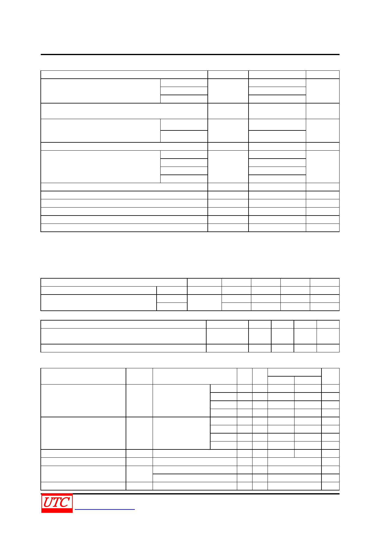
UT137FF/FG
TRIAC
ABSOLUTE MAXIMUM RATING
PARAMETER
SYMBOL
RATINGS
UNIT
UT137FF/FG-5
500(Note2)
Repetitive Peak Off-State Voltages
UT137FF/FG-6
VDRM
600(Note2)
V
UT137FF/FG-8
800
RMS On-state Current
Full sine wave, THS ≤92C
IT(RMS)
8
A
Non-Repetitive Peak. On-State Current
t =20 ms
55
Full sine wave, TJ =125C prior to surge, with
ITSM
A
reapplied VDRM(MAX)
t =16.7 ms
60
I2t For Fusing (t =10 ms)
I2t
21
A2s
Repetitive Rate of Rise of On-state Current
after Triggering
ITM=12 A, IG=0.2 A, dIG/dt=0.2A/µs
T2 + G+
T2 + G-
T2 - G-
T2 - G+
dIT /dt
50
50
50
A/µs
10
Peak Gate Voltage
VGM
5
V
Peak Gate Current
Peak Gate Power
IGM
PGM
2
A
5
W
Average Gate Power (Over any 20ms period)
Operating Junction Temperature
PG(AV)
0.5
W
TJ
125
°C
Storage Temperature
TSTG
-40 ~ +150
°C
Notes: 1. Absolute maximum ratings are those values beyond which the device could be permanently damaged.
Absolute maximum ratings are stress ratings only and functional device operation is not implied.
2. Although not recommended, off-state voltages up to 800V may be applied without damage, but the triac
may switch to the on-state. The rate of rise of current should not exceed 6A/µs.
THERMAL RESISTANCES
PARAMETER
SYMBOL
MIN
TYP
MAX
UNIT
Thermal resistance Junction to Ambient
In Free Air
θJA
Thermal resistance Junction to mounting
base
Full cycle
Half cycle
θJC
55
°C/W
4.5
°C/W
6.5
°C/W
ISOLATION LIMITING VALUE & CHARACTERISTIC (THS =25C, unless otherwise specified)
PARAMETER
SYMBOL
MIN TYP MAX UNIT
Repetitive peak voltage form all three terminals to external
heatsink (R.H.≤ 65%,clean and dustfree)
VISOL
1500
V
Capacitance from MT2 to external heatsink (f =1MHz)
CISOL
12
pF
STATIC CHARACTERISTICS (TJ=25°C, unless otherwise specified)
PARAMETER
Gate Trigger Current
Latching Current
Holding Current
On-State Voltage
Gate Trigger Voltage
Off-State Leakage Current
SYMBOL
TEST CONDITIONS
T2 + G+
IGT VD =12 V,IT =0.1A
T2 + G-
T2 - G-
T2 - G+
T2 + G+
IL
VD =12 V,IGT =0.1A
T2 + G-
T2 - G-
T2 - G+
IH VD =12 V,IGT =0.1A
VT IT =10 A
VGT
VD=12V, IT =0.1A
VD=400V, IT=0.1A, TJ=125°C
ID
VD=VDRM(MAX), TJ =125°C
MIN
TYP
MAX
UT137FF UT137FG
UNIT
5
25
50
mA
8
25
50
mA
11
25
50
mA
30
70
100 mA
7
20
45
mA
16
30
60
mA
5
45
45
mA
7
30
60
mA
5
20
40
mA
1.3
1.65
V
0.7
1.5
V
0.25 0.4
V
0.1
0.5
mA
UNISONIC TECHNOLOGIES CO., LTD
www.unisonic.com.tw
2 of 6
QW-R401-016.C
Share Link: 