TSL2581CS Ver la hoja de datos (PDF) - austriamicrosystems AG
Número de pieza
componentes Descripción
Fabricante
TSL2581CS Datasheet PDF : 33 Pages
| |||
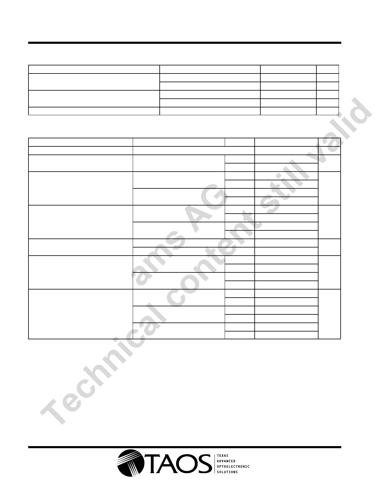
TSL2581, TSL2583
LIGHT-TO-DIGITAL CONVERTER
TAOS134A − JULY 2012
Electrical Characteristics over recommended operating free-air temperature range (unless
otherwise noted)
PARAMETER
TEST CONDITIONS
MIN TYP MAX UNIT
IDD Supply current
Active
Power down — I2C activity
175 250 μA
3
10 μA
3 mA sink current
0
0.4 V
VOL INT, SDA output low voltage
I LEAK Leakage current
6 mA sink current
0
0.6 V
−5
5 μA
lid Operating Characteristics, VDD = 3 V, TA = 255C, (unless otherwise noted) (Notes 1, 2, 3, and 4)
PARAMETER
TEST CONDITIONS
CHANNEL
MIN TYP MAX UNIT
a fosc Oscillator frequency
v Dark ADC count value
Ee = 0, ATIME = 0xB6 (200 ms),
gain = 16×
705 750 795 kHz
Ch0
0
1
5
counts
Ch1
0
1
5
Ch0
ill ATIME = 0xDB (100 ms)
Ch1
Full scale ADC count value
Ch0
ATIME = 0x6C (400 ms)
t Ch1
37887
37887
65535
65535
counts
AG t s ADC count value
λp = 625 nm, ATIME = 0xF6 (27 ms)
Ch0
Ee = 171.6 μW/cm2, gain = 16×
Ch1
λp = 850 nm, ATIME = 0xF6 (27 ms)
Ch0
Ee = 220 μW/cm2, gain = 16×
Ch1
4000
4000
5000
700
5000
2750
6000
counts
6000
s n ADC count value ratio: Ch1/Ch0
λp = 625 nm
λp = 850 nm
am nte Re Irradiance responsivity
Ch0
λp = 625 nm, ATIME = 0xF6 (27 ms)
Ch1
Ch0
λp = 850 nm, ATIME = 0xF6 (27 ms)
Ch1
10.8 15.8 20.8
%
41
55
68
29.1
4
counts/
(μW/
22.8
cm2)
12.5
Ch0
7
8
9
o 8×
Ch1
7
8
9
c Gain scaling (relative to 1×)
16×
Ch0
15
16
17
×
Ch1
15
16
17
l111×, decoupling capacitor 25 mm
Ch0
afrom VDD pin (Note 5)
Ch1
97 107 115
100 115 125
NOTES: 1. Optical measurements are made using small-angle incident radiation from light-emitting diode optical sources. Visible 640 nm LEDs
ic and infrared 850 nm LEDs are used for final product testing for compatibility with high-volume production.
2. The 625 nm irradiance Ee is supplied by an AlInGaP light-emitting diode with the following characteristics: peak wavelength
λp = 625 nm and spectral halfwidth Δλ½ = 20 nm.
3. The 850 nm irradiance Ee is supplied by a light-emitting diode with the following characteristics: peak wavelength
n λp = 850 nm and spectral halfwidth Δλ½ = 42 nm.
4. The integration time Tint, is dependent on internal oscillator frequency (fosc) and on the number of integration cycles (ATIME) in the
h Timing Register (0xFF) as described in the Register section. For nominal fosc = 750 kHz, nominal Tint = 2.7 ms × ATIME.
5. 111× gain is affected by the line inductance between the VDD pin and the decoupling capacitor. See Figure 3 for 111× gain scale
Tec versus line inductance characteristic.
Copyright E 2012, TAOS Inc.
4
r
www.taosinc.com
The LUMENOLOGY r Company
r
Share Link: 