SD263C30S50L(2018) Ver la hoja de datos (PDF) - Vishay Semiconductors
Número de pieza
componentes Descripción
Fabricante
SD263C30S50L Datasheet PDF : 8 Pages
| |||
www.vishay.com
VS-SD263C..S50L Series
Vishay Semiconductors
FORWARD CONDUCTION
PARAMETER
Maximum average forward current
at heatsink temperature
Maximum RMS forward current
Maximum peak, one-cycle forward,
non-repetitive surge current
SYMBOL
IF(AV)
IF(RMS)
IFSM
Maximum I2t for fusing
I2t
Maximum I2t for fusing
Low level value of threshold voltage
High level value of threshold voltage
Low level value of forward slope resistance
High level value of forward slope resistance
Maximum forward voltage drop
I2t
VF(TO)1
VF(TO)2
rf1
rf2
VFM
TEST CONDITIONS
180° conduction, half sine wave
Double side (single side) cooled
25 °C heatsink temperature double side cooled
t = 10 ms No voltage
t = 8.3 ms reapplied
t = 10 ms
t = 8.3 ms
t = 10 ms
t = 8.3 ms
50 % VRRM
reapplied
No voltage
reapplied
Sinusoidal half wave,
initial TJ = TJ
maximum
t = 10 ms 50 % VRRM
t = 8.3 ms reapplied
t = 0.1 to 10 ms, no voltage reapplied
(16.7 % x x IF(AV) < I < x IF(AV)), TJ = TJ maximum
(I > x IF(AV)), TJ = TJ maximum
(16.7 % x x IF(AV) < I < x IF(AV)), TJ = TJ maximum
(I > x IF(AV)), TJ = TJ maximum
Ipk = 1000 A, TJ = TJ maximum,
tp = 10 ms sinusoidal wave
VALUES
375 (150)
55 (85)
725
5500
5760
4630
4850
151
138
107
98
1510
1.56
1.71
1.64
1.53
3.20
UNITS
A
°C
A
kA2s
kA2s
V
mW
V
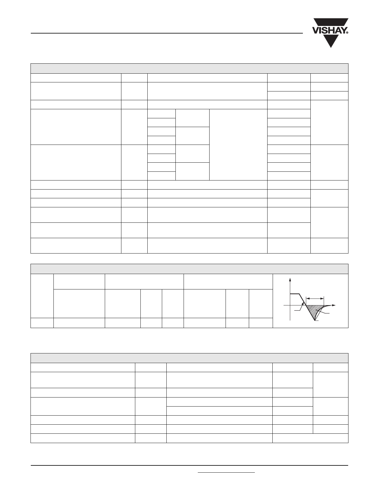
RECOVERY CHARACTERISTICS
CODE
MAXIMUM VALUE
AT TJ = 25 °C
trr AT 25 % IRRM
(μs)
TEST CONDITIONS
Ipk
SQUARE dI/dt (1) Vr
PULSE
(A/μs) (V)
(A)
S50
5.0
1000
100 - 50
TYPICAL VALUES
AT TJ = 150 °C
trr AT 25 % IRRM Qrr
Irr
(μs)
(μC)
(A)
4.5
680
240
Note
(1) dI/dt = 25 A/μs, TJ = 25 °C
IFM
trr
dir
t
dt
Qrr
IRM(REC)
THERMAL AND MECHANICAL SPECIFICATIONS
PARAMETER
SYMBOL
TEST CONDITIONS
Maximum junction operating
temperature range
TJ
Maximum storage temperature range
Maximum thermal resistance,
junction to heatsink
TStg
RthJ-hs
DC operation single side cooled
DC operation double side cooled
Mounting force, ± 10 %
Approximate weight
Case style
See dimensions - link at the end of datasheet
VALUES
UNITS
-40 to 125
°C
-40 to 150
0.11
K/W
0.05
9800 (1000)
N (kg)
230
g
B-PUK (DO-200AB)
RthJ-hs CONDUCTION
CONDUCTION ANGLE
SINUSOIDAL CONDUCTION
SINGLE SIDE DOUBLE SIDE
180°
0.012
0.011
120°
0.014
0.015
90°
0.018
0.018
60°
0.026
0.027
30°
0.045
0.046
RECTANGULAR CONDUCTION
SINGLE SIDE DOUBLE SIDE
0.008
0.008
0.014
0.014
0.019
0.019
0.027
0.028
0.046
0.046
TEST CONDITIONS
TJ = TJ maximum
UNITS
K/W
Note
• The table above shows the increment of thermal resistance RthJ-hs when devices operate at different conduction angles than DC
Revision: 11-Jan-18
2
Document Number: 93173
For technical questions within your region: DiodesAmericas@vishay.com, DiodesAsia@vishay.com, DiodesEurope@vishay.com
THIS DOCUMENT IS SUBJECT TO CHANGE WITHOUT NOTICE. THE PRODUCTS DESCRIBED HEREIN AND THIS DOCUMENT
ARE SUBJECT TO SPECIFIC DISCLAIMERS, SET FORTH AT www.vishay.com/doc?91000
Share Link: 