RMLA3565-58 Ver la hoja de datos (PDF) - Raytheon Company
Número de pieza
componentes Descripción
Fabricante
RMLA3565-58 Datasheet PDF : 4 Pages
| |||
RMLA3565-58
RF Components Wideband Low Noise MMIC Amplifier
PRODUCT INFORMATION
Figure 3
Schematic for a
Typical Test
Evaluation Board
(RMLA3565-58-TB)
RF in
J1
Ray
RMLA3565
-58
RF out
J2
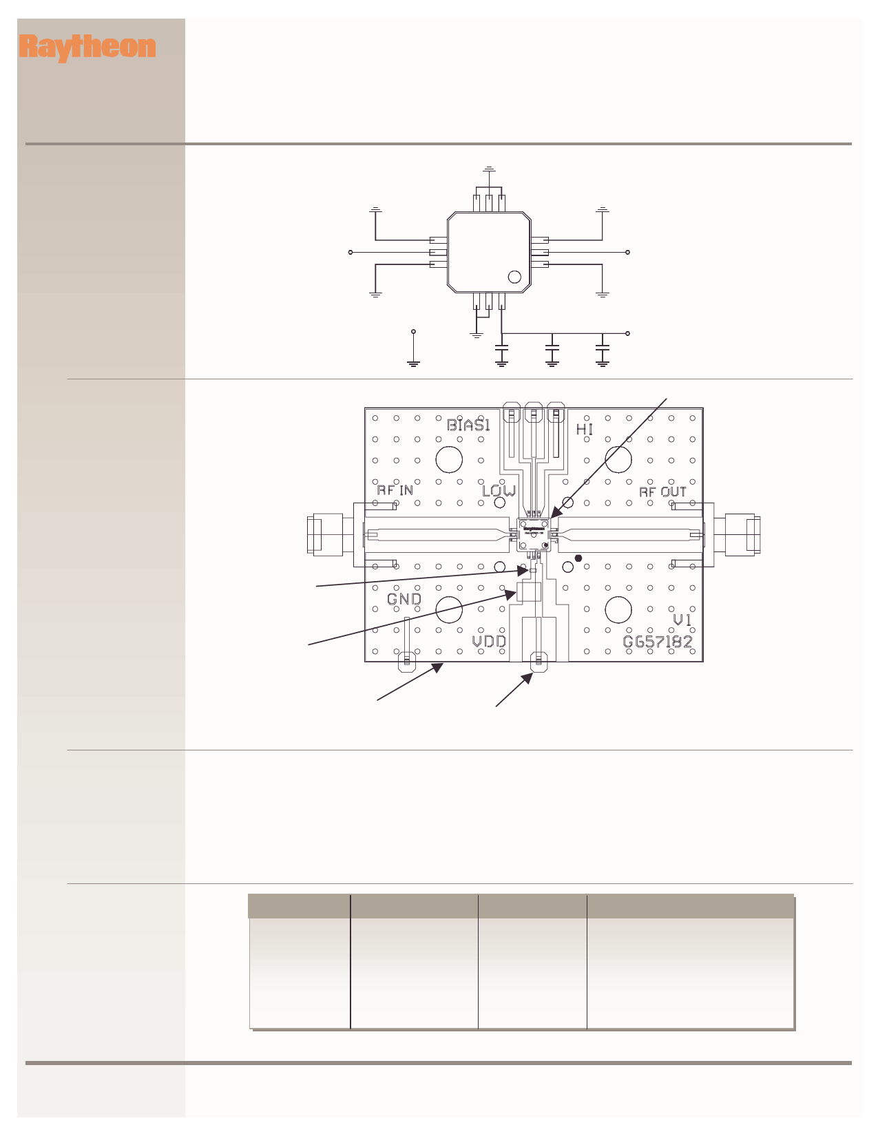
Figure 4
Layout and Assembly of
Test Evaluation Board
(RMLA3565-58-TB)
GND
P2
RF In
J1
C1
(Opt)
C2
C3
(OPT)
Vdd
P1
U1
RF Out
J2
C1 & C2
(OPT)
C3
Ground
(GND) P2
Vdd P1
Test Procedure
for the evaluation board
(RMLA3565-58-TB)
Parts List
for test evaluation board
RMLA3565-58-TB)
The following sequence of procedure must be followed to properly test the power amplifier:
Step 1: Turn off RF input power.
Step 2: Use GND terminal of the evaluation board
to connect DC supply grounds.
Step 3: Apply drain supply voltage of +4.0 V to
evaluation board terminal Vdd.
Step 4:
After the bias condition is
established, RF input signal may now be
applied.
Step 5:
Follow turn-off sequence of:
(i) Turn off RF input power.
(ii) Turn down and off Vdd.
Part
C1
C2
C3
U1
P1, P2
J1, J2
Board
Value
330 pF
1000 pF
4.75 uF
RMLA3565-58
Terminal
SMA Connectors
RO4003(Rogers)
EIA Size
.04” x .02”
.04” x .02”
.14”x .11”
.28” x .28” x .07”
1.99x1.50x.032
Vendor(s)
AVX, Murata, Novacap,
AVX, Murata, Novacap
Sprague, ATC, AVX, Murata
Raytheon
Samtec
E.F. Johnson
Raytheon
www.raytheonrf.com
Specifications are based on most current or latest revision.
Revised February 6, 2003
Page 3
Raytheon RF Components
362 Lowell Street
Andover, MA 01810
Share Link: 