RMLA3565-58(2001) Ver la hoja de datos (PDF) - Raytheon Company
Número de pieza
componentes Descripción
Fabricante
RMLA3565-58 Datasheet PDF : 5 Pages
| |||
RMLA3565-58
Wideband Low Noise MMIC Amplifier
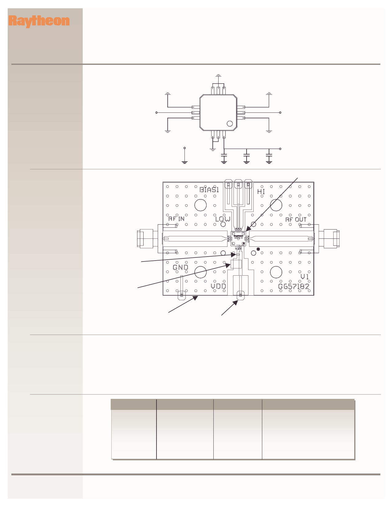
Figure 3
Schematic for a Typical
Test Evaluation Board
(RMLA3565-58-TB)
RF in
J1
-58
PRELIMINARY INFORMATION
RF out
J2
Figure 4
Layout and Assembly of
Test Evaluation Board
(RMLA3565-58-TB)
GRND
P2
C2
C3
(OPT)
Vdd
P1
C1
U1
RF In
J1
RF Out
J2
C1 & C2
(OPT)
C3
Ground
(GND) P2
Vdd P1
Test Procedure
for the evaluation board
(RMLA3565-58-TB)
The following sequence of procedure must be followed to properly test the power amplifier:
Step 1: Turn off RF input power.
Step 2: Use GND terminal of the evaluation board for
DC supplies.
Step 3: Apply drain supply voltages of +4.0 V to
evaluation board terminal Vdd.
Step 4: After the bias condition is established, RF input
signal may now be applied.
Step 5: Follow turn-off sequence of:
(i) Turn off RF Input Power
(ii) Turn down and off Vdd
Parts List
for Test Evaluation Board
(RMLA3565-58-TB)
Part
C1
C2
C3
U1
P1, P2
J1, J2
Board
Value
330 pF
1000 pF
4.75 uF
RMLA3565-58
Terminal
SMA Connectors
RO4003(Rogers)
EIA Size
.04” x .02”
.04” x .02”
.14”x .11”
.28” x .28” x .07
1.99x1.50x.032
Vendor(s)
AVX, Murata, Novacap,
AVX, Murata, Novacap
Sprague, ATC, AVX, Murata,
Raytheon
Samtec
E.F. Johnson
Raytheon
www.raytheon.com/micro
Characteristic performance data and specifications are subject to change without notice.
Revised September 24, 2001
Page 3
Raytheon RF Components
362 Lowell Street
Andover, MA 01810
Share Link: 